
5G and LTE Integration Testing with NFAPI and OAI UEs: Architecture and Simulation Explained

5G–LTE Integration Testing Framework: How NFAPI, OAI UEs, and Channel Proxy Enable Multi-RAT Simulation
As we move from LTE (4G) to 5G NR (New Radio), testing and validating networks has become more complicated. It's crucial for modern telecom systems to make sure that older LTE technology works seamlessly with the new 5G setups, especially in Non-Standalone (NSA) mode, where both systems run side by side.
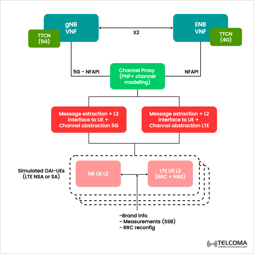
The diagram uploaded gives a clear look at how the gNB (5G node) and eNB (LTE node) are linked together in a simulated setting using Virtual Network Functions (VNFs), NFAPI interfaces, and OAI-based simulated UEs.
Let’s take a closer look at this architecture to understand how we test and validate the interworking between 5G and LTE in either a lab or cloud-based simulation.
Overview: LTE and 5G Integration in NSA Mode
In NSA (Non-Standalone) mode, the eNB (LTE base station) serves as the anchor node for control signaling, while the gNB (5G base station) handles user data through fast NR channels. This combination lets operators roll out 5G faster without completely replacing their LTE infrastructure.
However, when it comes to testing, using real base stations and UEs isn’t practical. So, we rely on virtualized network functions (VNFs) and simulated UEs to recreate how LTE and 5G layers interact.
This structure is foundational for multi-RAT (Radio Access Technology) integration testing using NFAPI, X2, and OAI-based simulation.
Key Components in the Integration Framework
The diagram outlines several key elements involved in 4G–5G integration testing:
Component Function
gNB VNF (5G): Simulates functions of the 5G base station (NR PHY/MAC/PDCP layers).
eNB VNF (4G): Simulates the LTE base station for control-plane anchoring.
TTCN (5G/4G): A test suite that manages and validates signaling between nodes.
Channel Proxy (PNF + Channel Modeling): Simulates physical network functions and RF conditions.
NFAPI Interface: Facilitates communication between VNFs and the channel proxy for functional splits.
X2 Interface: Enables interworking between eNB and gNB in NSA setups.
Simulated OAI-UEs: Mimics user equipment (UE) behavior for both LTE and 5G layers.
Role of NFAPI and Channel Proxy
NFAPI (Network Functional Application Platform Interface)
NFAPI serves as a vital interface defined by the Small Cell Forum to standardize how a centralized baseband (VNF) communicates with distributed radio units (PNFs). Here’s how it works:
The eNB/gNB VNF handles upper-layer processing (MAC, RLC, PDCP).
The Channel Proxy (PNF) takes care of lower-layer physical functions, channel abstraction, and signal modeling.
This division makes it possible to perform realistic functional split testing (often referred to as Option 6 or 7 split) in a virtualized RAN (vRAN) environment.
Channel Proxy and Channel Modeling
The Channel Proxy has two important jobs:
It acts as a bridge between NFAPI entities and UEs.
It simulates radio propagation effects like fading, delay, interference, and noise, creating a realistic testing environment.
This way, engineers can assess RRC signaling, throughput, and mobility performance under conditions that closely mimic real scenarios.
Interworking Between gNB and eNB via X2 Interface
The X2 interface is crucial for coordinating 4G and 5G, especially in EN-DC (E-UTRAN New Radio Dual Connectivity) situations, where:
The eNB (LTE) functions as the Master Node (MN).
The gNB (5G) serves as the Secondary Node (SN).
This connection allows for:
Control plane anchoring at LTE for backward compatibility.
A user plane split between LTE and NR to enhance throughput.
In the diagram, the bidirectional X2 link connects the gNB and eNB VNFs, allowing for handover procedures, load balancing, and bearer management.
Simulated OAI UEs: LTE and NR Layers
The lower part of the diagram shows Simulated OAI-UEs, which can function in both:
LTE mode (Standalone)
5G mode (NSA or SA)
OAI (Open Air Interface) is an open-source software stack for 5G/LTE, commonly used for research and development. It enables virtual UE simulation that interacts with VNFs through software-defined interfaces.
NR UE L2 and LTE UE L2
The NR UE L2 corresponds to the 5G Layer 2 stack, while LTE UE L2 deals with RRC (Radio Resource Control) and NAS (Non-Access Stratum) signaling. Both communicate with the VNFs via message extraction modules that abstract PHY behavior and manage L2/L3 communication.
Message Extraction and Channel Abstraction
On each side (5G and LTE), we have:
Message extraction: Capturing and interpreting control and user plane messages (RRC, PDCP, etc.).
L2 Interface to UE: Governing link-layer communication with the UE.
Channel abstraction: Modeling simplified PHY-layer effects without conducting complete RF simulations.
This approach significantly cuts down on testing complexity while still keeping functional accuracy intact.
End-to-End Test Workflow
Here’s how the integration testing process plays out step by step:
Initialization: * The gNB VNF and eNB VNF are set up as virtual nodes. * NFAPI establishes the connection to the Channel Proxy.
X2 Setup: * eNB and gNB share X2 setup messages to enable EN-DC coordination.
UE Simulation: * OAI-based UEs (NR UE L2 and LTE UE L2) are activated. * The LTE UE manages RRC setup while the NR UE validates the data plane.
Message Processing: * The system extracts and processes signaling and data messages from both ends. * Measurement reports, SSB (Synchronization Signal Blocks), and RRC reconfigurations are exchanged.
Channel Modeling: * The Channel Proxy introduces path loss, delay spread, or fading models. * This helps validate network resilience and adaptive modulation logic.
KPIs and Verification: * TTCN scripts (4G/5G) execute conformance and performance tests. * Metrics like latency, throughput, and handover success are logged.
Information Exchange Between LTE and 5G Layers
The dotted lines joining the LTE and NR UE layers represent cross-layer signaling. The data exchanged includes:
Brand Info: Identification and synchronization parameters between LTE and NR.
Measurements (SSB): Signal strength and quality reports for NR synchronization.
RRC Reconfiguration: Updates to connection parameters during EN-DC or handover.
These exchanges ensure smooth Dual Connectivity operations and effortless handover or bearer split in real-world scenarios.
Benefits of the Simulation Framework
Advantage Description
Cost Efficiency: No need for physical gNB/eNB hardware; everything is virtualized.
Flexibility: Supports NSA and SA configurations.
Repeatability: Allows identical conditions for multiple test runs.
Extensibility: Easily fits with other virtual network functions or SDN controllers.
Automation Ready: TTCN enables automated test execution and result gathering.
This setup is perfect for R&D labs, operator validation testing, and university research projects exploring future 5G/6G network potential.
- Real-World Applications
This LTE–5G testing framework finds applications in:
RAN integration testing for EN-DC deployment.
vRAN and O-RAN functional verification.
5G Core interworking validation.
Algorithm testing for scheduling, mobility, and interference management.
SDN-based orchestration and cloud-native RAN design.
Conclusion
The showcased LTE–5G integration testing framework presents a dynamic, virtualized approach for validating dual connectivity and interoperability. By combining NFAPI-based VNFs, channel proxy modeling, and OAI UEs, engineers can replicate real-world situations— from control plane anchoring to RRC reconfiguration— without needing physical infrastructure.
This architecture signifies the next wave in network testing, offering quick, cost-effective validation of multi-RAT systems as we gear up for a full 5G Standalone rollout.
As the telecom world shifts toward Open RAN and cloud-native setups, simulation frameworks like this will continue to be essential for ensuring interoperability, performance, and innovation across various technology landscapes.