
5G NR MAC PDU Structure Explained: Understanding DL and UL MAC PDU Examples

Grasping the Structure of 5G NR MAC PDU: A Look at DL and UL Examples
In 5G New Radio (NR), the Medium Access Control (MAC) layer is crucial for managing how data gets packaged, scheduled, and sent between the physical layer (PHY) and the upper layers. The MAC PDU (Protocol Data Unit) is the key data structure exchanged between the User Equipment (UE) and the Next Generation Node B (gNB) over the air.
This article goes through the DL (Downlink) and UL (Uplink) MAC PDU structures as shown in the image above, breaking down each part—from MAC sub headers to Control Elements (CEs) and Service Data Units (SDUs).
What’s a MAC PDU in 5G NR?
In the 5G MAC layer, the data coming from the upper layers (like RLC or SDAP) is wrapped into MAC PDUs before reaching the physical layer. Each MAC PDU can include:
MAC Control Elements (MAC CEs) for control signaling
MAC SDUs for user or control plane data
Padding bits for alignment purposes
The MAC layer is in charge of mixing these elements together, making sure data transmission is efficient and resources are used well.
Overview of 5G MAC PDU Structure
Each MAC PDU comprises:
MAC Sub headers
MAC Sub PDUs (which can include a CE, SDU, or padding)
Every MAC PDU kicks off with a sub header, which tells you what data type and size comes next.
Structure of the MAC PDU
+———————————————————+| Sub header | MAC SDU or MAC CE | Sub header | MAC SDU ... |+—— —————————————————+
Key Elements:
Sub header (R/F/L/CID/L Fields): Specifies the format and type of content.
MAC CE (Control Element): Carries control info for the MAC layer.
MAC SDU (Service Data Unit): Holds upper-layer payloads (like RLC PDUs).
Padding: Used for alignment when necessary.
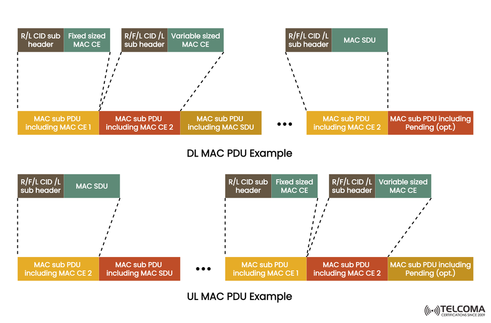
Breaking Down the DL MAC PDU Example
The Downlink MAC PDU (DL MAC PDU) represents data sent from the gNB to the UE. As depicted in the diagram, it has a series of sub headers and sub-PDUs that carry control and data information.
Components of the DL MAC PDU Example:
R/L CID Sub header and Fixed-Sized MAC CE
The R/L bits show if there are more sub headers.
CID points to the logical channel.
Fixed-size MAC CE contains control info of a set length (like power control commands).
R/F/L CID/L Sub header and Variable-Sized MAC CE
The R/F/L bits define properties of the sub header.
Variable-sized MAC CE carries control elements like DRX commands or Buffer Status Reports (BSRs).
R/F/L CID/L Subheader and MAC SDU
Represents the payload or data from the RLC layer intended for the UE.
Pending (Optional) MAC Sub PDU
Used for optional or pending control elements.
Helps in aligning PDUs or sending additional signaling data.
Typical Control Elements in DL PDUs
Timing Advance Command CE
Power Headroom Report CE
DRX Command CE
These control elements keep things synchronized, optimize uplink scheduling, and manage power effectively.
Unpacking the UL MAC PDU Example
The Uplink MAC PDU (UL MAC PDU) is the structure used for data sent from the UE to the gNB. It shares a similar layout with the DL PDU but may include uplink-specific control elements like BSRs and scheduling requests.
Components of the UL MAC PDU Example:
R/F/L CID/L Sub header and MAC SDU
This covers the uplink RLC data sent by the UE.
Identifying the logical channel ensures the data reaches the right bearer.
MAC Sub PDU including MAC CE
Contains control messages specific to uplink (like Buffer Status Report CE).
Fixed and Variable-sized MAC CEs
Fixed-size CE: e.g., Power Headroom Report (PHR)
Variable-size CE: e.g., Long BSR or Short BSR based on buffer status.
Optional Pending Sub-PDU
Manages additional control signaling or padding for alignment.
Explaining MAC Sub header Fields
Every MAC sub header lays out vital control information to help interpret the following sub-PDU.
Field Description
R (Reserved): Always set to 0; saved for future use
F (Format): Tells if the L field exists (length of payload)
L (Length): Indicates the size of the MAC SDU or MAC CE
LCID (Logical Channel ID): Points to the logical channel (like DCCH, DTCH)
Note:
LCID values 0–31 specify logical channels.
LCID values 32–63 are allocated for MAC CEs.
MAC Control Elements (MAC CEs)
MAC CEs are control messages shared between the UE and gNB for managing the MAC level. They don’t pass through the RLC layer.
Common MAC CEs and What They Do:
MAC CE Type Side Purpose
Buffer Status Report (BSR) UL Tells how much uplink data is waiting in UE buffers
Power Headroom Report (PHR) UL Shares available power to aid link adaptation
Timing Advance Command (TAC) DL Adjusts uplink timing for staying in sync
DRX Command CE DL Manages Discontinuous Reception states
BSR Triggers CE UL Communicates scheduling needs
Differences Between DL and UL MAC PDUs
Feature DL MAC PDU (gNB → UE)UL MAC PDU (UE → gNB) Direction Downlink Uplink Control Elements (CEs)DRX, TAC, power control BSR, PHR Data Type RLC SDUs from g NB RLC SDUs from UE Pending Field Optional for extra signaling Optional for padding Purpose Delivers user data & control Reports status & sends data
How MAC PDUs Enhance 5G Efficiency
The flexible design of MAC PDUs in 5G enables:
Efficient multiplexing of control and data info.
Dynamic scheduling for both uplink and downlink.
Lower overhead through compact sub headers.
Adaptive payload management with variable-length CEs.
This setup ensures high spectral efficiency, lower latency, and strong control signaling, especially in fluctuating network conditions.
Example: Multiplexing in DL MAC PDU
In downlink transmission, a single MAC PDU can carry:
A Power Headroom Report CE,
A DRX Command CE, and
Several RLC SDUs for user traffic — all packed into one frame.
This multiplexing cuts down on signaling overhead and boosts scheduling flexibility.
Real-World Applications of MAC PDU Design
Low-Latency Services:
Compact control signaling leads to faster scheduling decisions.
Massive IoT Deployments:
Efficiently manages small data packets via variable-length CEs.
Enhanced Mobile Broadband (eMBB):
Simultaneously sends large user data alongside control information.
Energy Efficiency:
DRX control with MAC CEs helps UEs conserve power while idle.
Final Thoughts
The 5G NR MAC PDU forms the backbone that connects the control and data planes at the MAC layer, ensuring smooth data transmission between UE and gNB. The DL and UL MAC PDU examples in the image show how various combinations of subheaders, MAC CEs, and SDUs contribute to flexibility, scalability, and reliability in 5G communication.
Grasping these details helps telecom engineers fine-tune throughput, cut down latency, and optimize scheduling in active 5G networks.
The MAC PDU might seem straightforward, but it’s a key design element that keeps the 5G system nimble, responsive, and efficient, whether it’s for smartphones, IoT devices, or self-driving networks.