
5G NR PDU Session Data Transfer Explained: Step-by-Step Signaling Flow Between UE, gNB, and 5G Core

5G NR PDU Session Data Transfer: A Detailed Look at Signaling
Once the 5G NR RRC Reconfiguration wraps up, it's time for the next big phase in the 5G connection: data transfer. This is when the User Equipment (UE) starts sending and receiving IP packets through an established PDU session.
The signaling sequence illustrated in the accompanying image shows how the data flow kicks off and is managed among the UE, gNB, and the 5G Core (5GC), which includes components like AMF, SMF, and UPF. Let’s dive into it step-by-step.
Understanding the 5G PDU Session Context
Before we jump into the signaling, let’s clarify some key components:
UE (User Equipment): This is the 5G device that sends uplink data and gets downlink packets.
gNB (Next Generation NodeB): It’s the 5G base station that handles the radio interface and relays data between the UE and the Core Network.
SMF (Session Management Function): This manages PDU session control, allocates IP addresses, and sorts out TEID management.
UPF (User Plane Function): It handles user-plane traffic and forwards data between the gNB and external networks.
TEID (Tunnel Endpoint Identifier): This identifies the GTP-U tunnels for data transport between network entities.
These pieces work together to keep data flowing smoothly between the UE and external networks.
Overview of the PDU Session Data Transfer Procedure
After the RRC Reconfiguration wraps up, both the 5G Core and gNB are set for data-plane establishment. The process kicks off when the gNB assigns tunnel identifiers for the PDU sessions and goes on to initiate data flow.
Here’s a look at the main signaling steps taken from the diagram.
Step-by-Step Signaling Flow
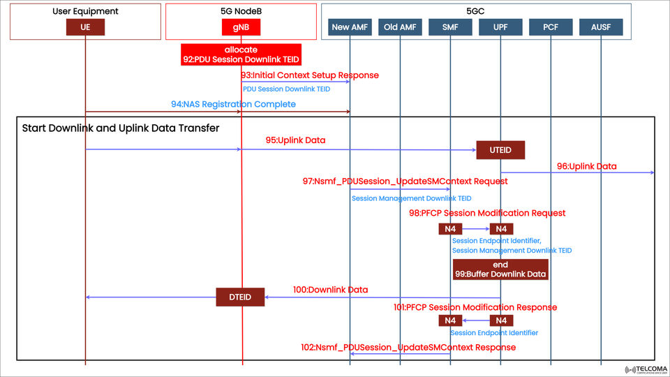
Step 92: PDU Session Downlink TEID Allocation
Action: The gNB allocates a PDU Session Downlink TEID.
Purpose: This TEID helps the UPF pinpoint the downlink data path to the gNB.
It makes sure that packets from the Core are routed correctly to the UE via the gNB.
Step 93: Initial Context Setup Response
Message: Initial Context Setup Response
Direction: gNB → AMF
This message confirms the gNB has successfully set up the UE context and resources for the PDU session.
It includes:
PDU Session Downlink TEID
Bearer configuration details
Radio resource status
At this stage, the network’s control plane is all set, and we’re ready to start transferring data.
Step 94: NAS Registration Complete
Message: NAS Registration Complete
Direction: UE → gNB → AMF
The UE confirms it’s successfully registered with the 5GC and is ready to transfer data.
Once this is acknowledged, both the control-plane and user-plane paths are good to go.
Kicking Off the Data Transfer
Step 95: Uplink Data Transmission Begins
The UE starts sending uplink data packets over the configured data radio bearers.
The data gets wrapped up in GTP-U (GPRS Tunneling Protocol - User Plane) before heading to the gNB.
The gNB maps the data using the uplink TEID (UTEID) and forwards it to the UPF via the N3 interface.
Step 96: Uplink Data Arrival at UPF
The UPF gets the uplink packets using the UTEID assigned earlier.
After receiving them, UPF sends them off to the external data network (DN), like the internet or a private network.
And this is where user data transfer officially kicks off in the uplink.
SMF Context Update for Session Management
Step 97: Ns mf _PDU Session_ Update SM Context Request
Message: Ns mf _PDU Session _Update SM Context Request
Direction: SMF → UPF
The SMF updates the session management info, which includes:
Session Management Downlink TEID
Session Endpoint Identifier
Purpose: To sync session parameters between the control plane (SMF) and user plane (UPF).
Step 98: PFCP Session Modification Request
Protocol: PFCP (Packet Forwarding Control Protocol)
Direction: SMF → UPF (via N4 interface)
This message modifies existing PFCP sessions to add new downlink and uplink TEIDs.
It also tells UPF to:
Buffer incoming downlink packets (if the UE isn’t quite ready)
Update QoS parameters or data forwarding rules
Step 99: Buffer Downlink Data
The UPF might temporarily buffer downlink data if the downlink TEID setup is still in progress.
This helps prevent packet loss while updating the session context.
Once everything's confirmed, the buffered packets are released toward the gNB.
Step 100: Downlink Data Transmission Begins
Direction: UPF → gNB → UE
The UPF uses the Downlink TEID (DTEID) to send buffered or new data packets to the gNB.
The gNB then passes this data to the UE over the air interface.
This is where bi-directional (uplink and downlink) user-plane traffic flow really kicks off.
Step 101: PFCP Session Modification Response
Direction: UPF → SMF (N4 interface)
Purpose: Acknowledges the successful update of PFCP rules and TEIDs.
Confirms the UPF is now set to route downlink packets to the gNB and uplink packets to the external network.
Step 102: Ns mf _ PDU Session _ Update SM Context Response
Direction: UPF → SMF
Content: Confirmation of the updated Session Management Context and TEID synchronization.
This wraps up the PDU session modification process and ensures the control-plane and user-plane states are in sync.
Steady-State Data Transfer Begins
Once both uplink and downlink tunnels are live:
UE → gNB → UPF handles uplink user data.
UPF → gNB → UE takes care of downlink user data.
At this point, data keeps flowing through the 5G NR radio bearers and GTP-U tunnels without needing more control-plane signaling. This steady state of data transfer continues until there’s a session change, termination, or handover to another gNB.
Key Protocols in This Process
Protocol Purpose Interface RRC (Radio Resource Control)Controls radio configurations between UE and g NBU u NAS (Non-Access Stratum)Manages registration and session establishment UE ↔ AMFPFCP (Packet Forwarding Control Protocol)Manages UPF session control SMF ↔ UPF (N4)GTP-U (GPRS Tunneling Protocol - User Plane)Carries actual user data g NB ↔ UPF (N3)
These protocols work together to make sure both signaling and user data transfer happen smoothly across all layers.
The Role of TEIDs in 5G Data Transfer
Tunnel Endpoint Identifiers (TEIDs) are super important for directing data through GTP-U tunnels. Each interface has its own unique TEID to keep traffic separate:
UTEID (Uplink TEID): Used by gNB to send user data to the UPF.
DTEID (Downlink TEID): This one’s for UPF to send data to the gNB.
TEIDs allow multiple PDU sessions to share the same transport path without issue.
This system helps manage data traffic efficiently for thousands of UEs at the same time.
Advantages of 5G PDU Session Design
The 5G PDU Session design offers several improvements over LTE:
It separates control and user planes, which allows for flexible scaling.
Dynamic QoS management is made possible through coordination between SMF and PCF.
Efficient session anchoring at the UPF ensures low-latency services.
Edge computing support can be achieved through local breakout at distributed UPFs.
Secure tunneling is accomplished with GTP-U encapsulation using TEIDs.
Conclusion
The 5G NR PDU Session Data Transfer process showcases the full potential of 5G — allowing for quick, seamless data exchange between devices and networks.
Thanks to the precise coordination among UE, gNB, and 5G Core entities (AMF, SMF, UPF), user data flows smoothly in both uplink and downlink traffic. Using PFCP, GTP-U, and TEIDs ensures that every piece of data gets where it needs to go quickly and securely through the 5G setup.
For telecom experts, understanding this signaling sequence is key to grasping how 5G networks fulfill their promise of ultra-reliable, low-latency communication.