
5G NR RRC Reconfiguration and PDU Session TEID Allocation Explained: Complete Data Transfer Flow

Understanding 5G NR RRC Reconfiguration and PDU Session TEID Allocation: A Comprehensive Overview
In a 5G Standalone (SA) network framework, moving from registration and authentication to actual data transfer entails a series of coordinated steps among the User Equipment (UE), gNB, and 5G Core (5GC).
This post breaks down how the 5G NR RRC Reconfiguration sets up the radio layer, how they allocate PDU Session TEIDs (Tunnel Endpoint Identifiers), and how data transfer kicks off over the user plane.
The illustrated flow connects the control plane of 5G (that includes RRC and NAS signaling) with the user plane (using GTP-U tunnels), providing a clear view of the signaling path and key message exchanges.
Overview: From Registration to Data Transfer
Once the UE has completed the following steps:
5G Registration
Authentication with AUSF/AMF
Security Mode Command (SMC)
Initial Context Setup
…it moves into the RRC Reconfiguration phase, which involves configuring the radio link and setting up the bearers. This lays the groundwork for establishing the PDU Session and starting data transfer through the User Plane Function (UPF).
Breaking Down the 5G NR RRC Reconfiguration Flow Step by Step
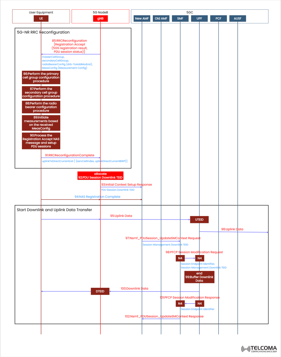
Let’s dive into the major steps as illustrated in the uploaded image.
Step 85: RRC Reconfiguration (Registration Accept, PDU Session Status)
The gNB sends an RRCReconfiguration message to the UE which includes:
Registration Accept message
PDU Session status information
Radio configuration parameters
This signals the UE’s shift from connection setup to being fully operational in an RRC-Connected state.
The RRC Reconfiguration message also carries:
master Cell Group (which defines the serving cell configuration)
secondary Cell Group (used for carrier aggregation or dual connectivity)
radio Bearer Config (setting up SRBs and DRBs)
Me as Config (measurement configuration necessary for mobility)
Steps 86–89: Configuring Radio and Cell Groups
These internal UE processes are key for ensuring that the radio and bearer layers are correctly set up before data transfer starts.
Step 86: Configuring the Primary Cell Group
Here, the UE sets up its primary cell group (PCell), which is the anchor cell that manages control signaling and scheduling for uplink/downlink.
Step 87: Configuring the Secondary Cell Group
If dual connectivity or carrier aggregation is in play, the UE will configure the secondary cell group (SCell) for extra bandwidth or multi-cell coordination.
Step 88: Configuring Radio Bearers
The UE establishes the radio bearers, which are logical channels responsible for carrying control and data traffic.
SRB (Signaling Radio Bearer): handles control-plane messages (like RRC and NAS)
DRB (Data Radio Bearer): transports user data
Step 89: Setting Up Measurement Configurations
The UE sets up measurement procedures to keep tabs on neighboring cells and support mobility events, such as handovers.
Step 90: Handling the Registration Accept NAS Message and Setting Up PDU Session
After completing RRC setup, the UE processes the NAS Registration Accept message (which is part of the RRC Reconfiguration).
At this point, the UE:
Confirms its registration with the 5G Core (AMF)
Establishes the PDU Session for data connectivity using the SMF and UPF
Step 91: Finalizing RRC Reconfiguration
The UE sends an RRC Reconfiguration Complete message back to the gNB, confirming the successful configuration of:
Radio parameters
Bearers (both SRB and DRB)
Measurement and mobility arrangements
It may also include uplink parameters like:
Uplink Direct Current List
Serving Cell Index
Uplink BWP (Bandwidth Part) configuration
With that, the UE is set to begin data transfer.
PDU Session TEID Allocation and Initial Context Setup Response
Following RRC reconfiguration, the user plane tunnel identifiers (TEIDs) are established to enable GTP-U tunneling between the gNB and UPF.
Step 92: Allocating the Downlink PDU Session TEID
The gNB allocates a Downlink TEID (DTEID) for GTP-U encapsulation of downlink data.
This TEID identifies the downlink tunnel from the UPF to the UE via the gNB.
Each PDU session comes with its own unique pair of uplink (UTEID) and downlink (DTEID) TEIDs.
Step 93: Initial Context Setup Response
The gNB sends an InitialContextSetupResponse message to the AMF, which includes:
PDU Session Downlink TEID
Status of the setup and identifiers
This completes the context establishment between the RAN and 5GC.
Step 94: Confirming NAS Registration Completion
The UE sends a NAS Registration Complete message to the AMF, confirming that both registration and context setup are complete.
Kicking Off Downlink and Uplink Data Transfer
With both control and user plane contexts up and running, the UE is ready to start exchanging user data.
Step 95: Sending Uplink Data
The UE sends uplink packets to the gNB, encapsulated with the Uplink TEID (UTEID).
This uplink data is then routed through:
gNB → UPF → Data Network (DN)
Step 96: Forwarding Uplink Data to UPF
The gNB passes the uplink data to the UPF over the N3 interface, where it’s decapsulated and directed to the appropriate external data network.
Step 97: Nsmf_PDU Session_Update SM Context Request
When the session state changes, the SMF sends an Nsmf_PDU Session_Update SM Context Request to the UPF, which includes:
Session Management Downlink TEID
PDU Session context information
This ensures that the UPF can accurately link downlink packets with the established TEIDs.
Step 98: PFCP Session Modification Request
The SMF dispatches a PFCP Session Modification Request (using the N4 interface) to the UPF carrying:
Session Endpoint Identifier
Downlink TEID
This informs the UPF to use the new TEID for downlink GTP-U tunnels.
Step 99: Buffering Downlink Data
While waiting for the PFCP response or session update to wrap up, the UPF might temporarily store incoming downlink packets to prevent data loss.
Step 100: Sending Downlink Data
Once the tunnel setup is confirmed, the UPF starts sending the buffered downlink packets through the GTP-U tunnel:
UPF → gNB (via N3) → UE
Step 101: Receiving PFCP Session Modification Response
The UPF sends a PFCP Session Modification Response back to the SMF, confirming that the new session context and downlink TEID have been successfully set up.
Step 102: Acknowledgment of Nsmf_PDU Session_Update SM Context Response
Finally, the SMF acknowledges to the AMF with an Nsmf_PDU Session_Update SM Context Response, indicating that both the control plane and user plane paths are now fully synced.
- Key Technical Insights
TEID (Tunnel Endpoint Identifier): A unique 32-bit value that identifies each GTP-U tunnel for both uplink and downlink traffic.
PFCP (Packet Forwarding Control Protocol): Responsible for managing session establishment and adjustments between SMF and UPF.
RRC Reconfiguration: Vital for activating DRBs and setting up measurement configurations related to mobility.
NAS Registration Complete: Marks the UE's full registration in the 5GC, with established data pathways.
Conclusion
The 5G NR RRC Reconfiguration and PDU Session TEID allocation mark a crucial transition from signaling to real data flow within a 5G Standalone network.
This process aligns both radio (RRC) and core (NAS, SMF, UPF) layers, ensuring:
Seamless establishment of user-plane
Secure data transfer
Optimized TEIDs for low-latency routing
Understanding each step—from RRC setup to PFCP session modification—allows telecom professionals to analyze call flows more effectively, troubleshoot data path issues, and enhance overall network performance.