
5G NR Standalone Access Registration: Understanding gNB Interactions and RRC Connection Setup

Explaining 5G Standalone Access Registration: Interactions with gNB and Setting Up RRC Connections
The 5G Standalone (SA) mode signifies a complete rollout of a 5G Core Network (5GC) without relying on LTE infrastructure. A crucial step in this setup is the Access Registration process, where the User Equipment (UE) makes its first connection with the gNB (5G NodeB).
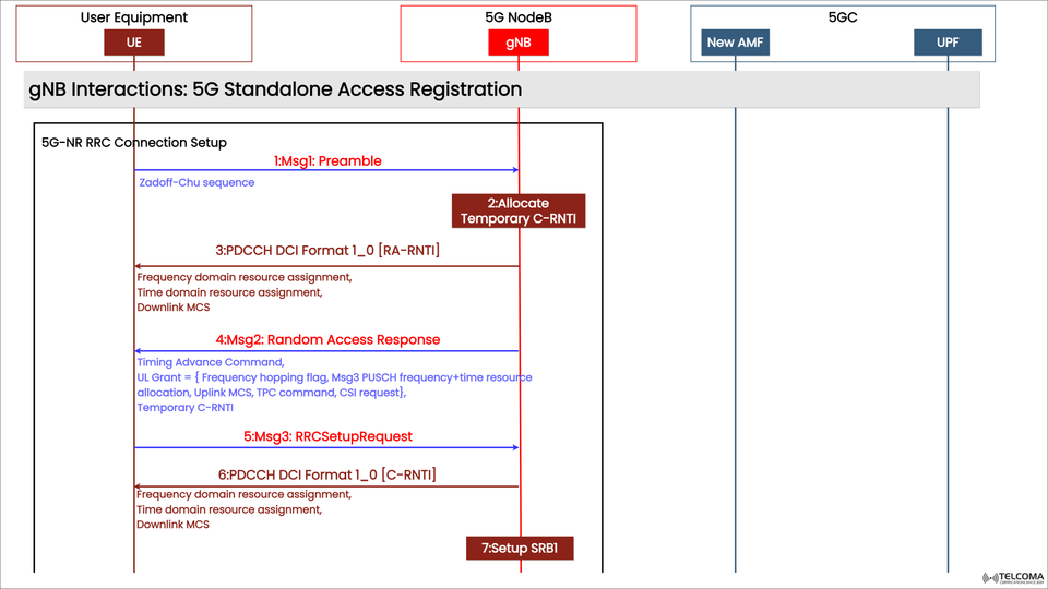
The diagram included shows this process in detail, focusing on how the UE and gNB communicate during the Random Access (RA) procedure and the initial RRC (Radio Resource Control) connection establishment.
In this post, we’ll break down each part of this signaling flow — from the Msg1 Preamble all the way to the Setup of SRB1 — explaining what happens, why it’s important, and how it gets 5G communication up and running.
Grasping the Basics: 5G Standalone Access Registration
The 5G SA Access Registration is the first step in forming a 5G NR connection. It involves things like:
Syncing the UE with the gNB,
Creating temporary identifiers and control channels, and
Setting up the first signaling bearer to exchange RRC and NAS messages.
This process ensures that the UE can communicate with the 5G network for authentication, security setup, and later data session establishment.
At this stage, the 5G Core (5GC) components like the Access and Mobility Management Function (AMF) and User Plane Function (UPF) are inactive — they come into play after the initial RRC connection is established.
Key Players Involved
Entity Role
UE (User Equipment) - Starts the access, sends preamble, requests RRC setup.
gNB (5G NodeB) - Manages Random Access, issues identifiers, schedules uplink/downlink.
AMF (Access and Mobility Management Function) - Oversees registration and mobility (involved later).
UPF (User Plane Function) - Manages user data traffic (involved later).
During this part, the UE interacts solely with the gNB, carrying out the Random Access procedure and setting up SRB1, which manages control-plane signaling.
Breaking Down the Process Step by Step
The image outlines seven key steps in the 5G NR RRC Connection Setup for standalone access registration.
Step 1: Msg1 – Preamble Transmission
Direction: UE → gNB
Purpose: Kicking off the Random Access procedure.
The UE starts by sending a preamble generated from a Zadoff-Chu sequence on the Physical Random Access Channel (PRACH).
This preamble allows the gNB to identify the UE’s presence and gauge the timing offset for synchronization.
Each preamble sequence is distinct within a cell.
It provides the basis for initial time and frequency alignment.
Once the gNB picks up the preamble, it assigns temporary identifiers.
Step 2: Allocate Temporary C-RNTI
Direction: Internal action of gNB
Purpose: Assigns a temporary identifier to the UE.
The gNB allocates a temporary Cell Radio Network Temporary Identifier (C-RNTI).
This identifier enables the UE to be uniquely addressed during the early connection setup stages.
This step doesn’t involve a direct over-the-air message but is rather an internal mapping within the gNB preparing for the Random Access Response.
Step 3: PD-CCH DCI Format 1_0 [RA-RNTI]
Direction: gNB → UE
The gNB transmits a Downlink Control Information (DCI) message on the Physical Downlink Control Channel (PDCCH) using RA-RNTI.
This DCI message includes:
Assignment of frequency-domain resources,
Allocation of time-domain resources,
Downlink Modulation and Coding Scheme (MCS).
In essence, it tells the UE how to go about receiving the upcoming Random Access Response (RAR).
Step 4: Msg2 – Random Access Response
Direction: gNB → UE
Purpose: Specifies uplink timing and grants resources.
The Random Access Response (RAR) comes with several key parameters:
Timing Advance Command: Adjusts the UE's transmission timing to sync with the gNB.
UL Grant: Defines the frequency and time resources for the UE’s next uplink message (Msg3).
Temporary C-RNTI: Confirms the identifier provided earlier.
TPC Command: Command for transmit power control for uplink transmission.
CSI Request: If needed, a request for Channel State Information.
This message ensures the UE is in sync and ready for controlled uplink communication.
Step 5: Msg3 – RRCSetupRequest
Direction: UE → gNB
Purpose: Kicks off the RRC connection setup.
After obtaining uplink resources from Msg2, the UE sends Msg3: RRC Setup Request using the PUSCH (Physical Uplink Shared Channel).
This message includes:
Establishment Cause (like Mobile Originated Data or Emergency Call),
UE identity (random or C-RNTI-based), and
Request for RRC connection establishment.
This is essentially the UE’s formal request to transition from the random access phase into a full RRC connection.
Step 6: PD-CCH DCI Format 1_0 [C-RNTI]
Direction: gNB → UE
Purpose: Provides updated scheduling information.
Once the gNB successfully gets Msg3, it sends another DCI Format 1_0, this time with the C-RNTI assigned.
This DCI encompasses:
Frequency-domain resource assignment,
Time-domain resource assignment,
Downlink MCS.
In simple terms, it tells the UE how to receive the upcoming RRC Setup message.
Step 7: Setup SRB1
Direction: Internal setup by gNB
Purpose: Establishes the first signaling bearer.
After confirming the Random Access process and exchanging RRC setup messages, the gNB establishes SRB1 (Signaling Radio Bearer 1).
SRB1 is used to carry:
RRC messages (control-plane), and
NAS messages between UE and AMF (once the registration continues).
This step wraps up the RRC Connection Setup phase, paving the way for further signaling linked to registration, authentication, and setting up data sessions.
Technical Highlights in the Process
a. Zadoff-Chu Sequence
The preamble utilizes a Zadoff-Chu sequence due to its constant amplitude and zero autocorrelation qualities — making it ideal for synchronization without interference.
b. Temporary vs Permanent C-RNTI
Initially, a temporary C-RNTI is given out. Once the RRC connection is completely established, it becomes the permanent C-RNTI for that UE within the cell.
c. Timing Advance
The gNB tweaks the UE’s transmission timing using the Timing Advance Command to offset propagation delays, ensuring uplink symbols arrive right on target.
d. Scheduling with DCI
The Downlink Control Information (DCI) messages are integral in 5G — they determine precisely when and how the UE should send or receive data.
Why This Stage Is Crucial
The Random Access and RRC Setup process guarantees:
Time and frequency sync between the UE and gNB.
Unique identification of the UE within the cell.
Uplink scheduling and control for future communication.
Establishment of SRB1 for NAS signaling with the Core Network.
Without this phase, the UE can’t progress to the RRCSetup, Security Mode Command, or NAS Registration stages that follow.
Simplified Overview of Message Flow
Step
Message
Direction
Key Function
1 Msg1: Preamble
UE → gNB
UE starts access
2 Temporary C-RNTI Allocation
gNB internal
Assign temporary ID
3 PD-CCH DCI [RA-RNTI]
gNB → UE
Scheduling info for RAR
4 Msg2: Random Access Response
gNB → UE
Timing advance, UL grant
5 Msg3: RRCSetupRequest
UE → gNB
UE requests RRC setup
6 PD-CCH DCI [C-RNTI]
gNB → UE
Resource scheduling
7 Setup SRB1
gNB internal
Establish signaling bearer
Notable Differences Between LTE and 5G Random Access
Feature
LTE
5G NR (Standalone)
Access Type
4-step RA procedure
Enhanced 4-step with flexible timing
Identifier
Temporary C-RNTI
Temporary then permanent C-RNTI
Channel
PRACH
PRACH (but supports beam-based access)
Scheduling
Basic DCI
Advanced DCI Format 1_0
Bearer Setup
SRB0, SRB1
Direct SRB1 setup is possible
5G brings in more flexibility for preamble transmission and scheduling, making it better suited for massive device density and low-latency applications.
Conclusion
The 5G NR Standalone Access Registration starts with this crucial RRC Connection Setup phase. Through messages Msg1 to Msg3 and related DCI scheduling, the UE syncs with the gNB, gains identifiers, and sets up its first signaling bearer — SRB1.
This process shifts the UE from being idle and unconnected to an active player in the 5G network, prepped for further steps like Security Mode Command, NAS Registration, and PDU Session Establishment.
By understanding these message flows, telecom professionals and enthusiasts can gain deeper insights into the accuracy and efficiency of 5G NR’s access mechanism — the vital foundation of next-gen connectivity.