
5G RRC Reconfiguration and Data Transfer Explained: Step-by-Step 5G Call Flow

Understanding the 5G-NR RRC Reconfiguration and Data Transfer Procedure
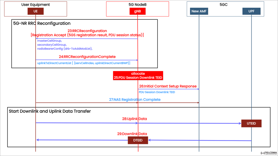
Once the 5G authentication and security setup are done, the network needs to configure the radio resources and data paths before any user traffic can actually flow. This is done through the 5G-NR RRC (Radio Resource Control) Reconfiguration procedure, followed by uplink and downlink data transfer.
The image above shows the signaling exchange among the User Equipment (UE), 5G NodeB (gNB), and 5G Core (5GC) — including the AMF and UPF.
Let’s break down each part of this process so we can grasp how a secure and efficient data session gets established in a 5G network.
Overview of 5G-NR RRC Reconfiguration
The RRC Reconfiguration process connects the control-plane setup (NAS and AS security) with the initiation of user-plane communication. It ensures that:
Radio bearers (SRB/DRB) are set up for user data.
PDU sessions are linked to the right radio resources.
The UE's uplink and downlink parameters match the network's setup.
Data Transfer Identifiers (TEIDs) are assigned to route traffic properly.
This procedure gets both the UE and gNB ready for smooth data exchange through the 5G Core’s UPF.
Network Entities Involved
Entity | Description
UE (User Equipment) | The device that starts and completes the RRC and data setup.
gNB (5G NodeB) | Handles radio resource configuration and forwards data between UE and 5GC.
AMF (Access and Mobility Management Function) | Manages registration, session management, and provides UE context to gNB.
UPF (User Plane Function) | Manages data forwarding and routing in the user plane (core network).
Step-by-Step 5G-NR RRC Reconfiguration and Data Flow
Let’s go through the signaling steps shown in the image.
Step 1: RRC Reconfiguration (Message 23)
Direction: gNB → UE
After completing the AS Security Mode procedures, the gNB sends an RRC Reconfiguration message to the UE. This message finalizes radio setup and includes:
Registration Accept (5GS registration result, PDU session status)
master Cell Group – Defines primary cell configuration.
secondary Cell Group – Used in dual connectivity situations.
radio Bearer Config (drb- To Add Mod List) – Adds or changes Data Radio Bearers (DRBs).
These settings determine how the data will be sent and received, ensuring that the UE’s radio interface aligns with the gNB’s scheduling and bandwidth setup.
👉 Purpose:
This message sets up radio bearers and signaling paths for the upcoming user data transfer.
Step 2: RRC Reconfiguration Complete (Message 24)
Direction: UE → gNB
Once the UE successfully applies the received configuration, it replies with RRC Reconfiguration Complete. This message confirms that:
Radio resources and bearers are correctly established.
Uplink transmission settings are active.
It also includes parameters like:
uplink Tx Direct Current List {serv Cell Index, uplink Direct Current BWP}, defining uplink cell indices and bandwidth parts.
👉 Purpose:
Confirms that the UE is set for active data communication with the configured resources.
Step 3: PDU Session Downlink TEID Allocation (Message 25)
Direction: gNB (internal action)
After confirming the RRC configuration, the gNB allocates a PDU Session Downlink TEID (Tunnel Endpoint Identifier).
The TEID identifies each data session tunnel between the gNB and UPF.
It ensures user data packets are correctly mapped to the UE’s session.
👉 Purpose:
To create a logical data tunnel for the user-plane connection between the gNB and UPF.
Step 4: Initial Context Setup Response (Message 26)
Direction: gNB → AMF
The gNB sends an Initial Context Setup Response to the AMF, confirming that the UE’s radio and session configurations are completed.
It includes:
PDU Session Downlink TEID
Resource setup status
👉 Purpose:
This response notifies the core network that the UE is now ready to send user-plane traffic.
Step 5: NAS Registration Complete (Message 27)
Direction: UE → AMF (via gNB)
The UE sends a NAS Registration Complete message, indicating that the registration and configuration processes have been successfully wrapped up.
At this moment:
The UE is fully authenticated.
NAS and AS security contexts are active.
Radio bearers and data tunnels are established.
👉 Purpose:
Marks the shift from control-plane setup to active data-plane communication.
Step 6: Start of Downlink and Uplink Data Transfer
With all setup stages done, data transfer kicks off.
(a) Uplink Data (Message 28)
Direction: UE → gNB → UPF
The UE sends user data packets using its Uplink TEID (UTEID).
The gNB maps these packets to the right tunnel and forwards them to the UPF for routing to the internet or service network.
(b) Downlink Data (Message 29)
Direction: UPF → gNB → UE
The UPF sends packets to the gNB using the Downlink TEID (DTEID).
The gNB identifies the correct UE session and delivers the packets via configured DRBs.
👉 Purpose:
This step marks the start of real-time 5G data flow, where user applications like browsing, video streaming, or VoIP begin to use the established radio link.
Data Flow Summary
Step Message Direction Key ParametersFunction23RRC Reconfiguration g NB → UE Radio Bearer Config, PDU Status Set up DRBs and radio resources24RRC Reconfiguration Complete UE → gNB Uplink Tx List Confirms successful setup25PDU Session Downlink TEID Internal TEID Allocation Creates data tunnels26Initial Context Setup Responseg NB → AMF Downlink TEID Confirms radio/session setup27NAS Registration Complete UE → AMF-Completes registration28Uplink Data UE → UPFUTEID Starts uplink traffic29Downlink Data UPF → UEDTEID Starts downlink traffic
Key Concepts: TEIDs and Data Tunneling
TEID (Tunnel Endpoint Identifier) is essential for mapping data sessions in 5G:
UTEID (Uplink TEID): Identifies uplink data from UE → UPF.
DTEID (Downlink TEID): Identifies downlink data from UPF → UE.
These identifiers ensure that each packet is matched to the correct PDU session, allowing multiple sessions (like voice and data) to run simultaneously without interference.
Why RRC Reconfiguration is Critical
🧩 Bridges Control and User Plane: It shifts from signaling setup to active data transfer.
⚙️ Optimizes Radio Resources: Assigns bandwidth and bearer configurations for smooth throughput.
🔐 Maintains Security: Functions under established NAS and AS security contexts.
🌐 Supports Multiple Sessions: Manages several PDU sessions with unique TEIDs.
🚀 Ensures Service Readiness: The UE is fully set for internet and application traffic.
Troubleshooting Insights for Engineers
Common issues during RRC Reconfiguration and Data Transfer include:
RRC Reconfiguration Failure: Often due to mismatched DRB config or UE capability issues.
Missing TEID Mapping: Can lead to no data flow between gNB and UPF.
Registration Complete Missing: UE doesn't reach CM-CONNECTED state.
Data Plane Blockage: Check the S1-U (or N3) interface for tunnel misconfigurations.
Tip: Always check the UE's radio bearer setup via logs (RRC, NAS traces) and confirm TEID mapping consistency between gNB and UPF.
End-to-End Process Recap
NAS & AS Security Setup → Secure signaling established.
Initial Context Setup → UE context and keys delivered to gNB.
RRC Reconfiguration → Configures radio bearers and resources.
NAS Registration Complete → Confirms registration and setup success.
Data Transfer Begins → Uplink and downlink flows start using TEIDs.
Conclusion
The 5G-NR RRC Reconfiguration and Data Transfer Procedure signifies the final step in getting a UE ready for real 5G communication. It combines radio configuration, session establishment, and TEID-based tunneling to facilitate smooth, secure, and high-speed data exchange.
By understanding how each message — from RRC Reconfiguration to Downlink Data — plays a role in the 5G call flow, telecom professionals can troubleshoot issues, optimize performance, and ensure reliable service delivery in today’s 5G networks.