
5G SMF Interactions Explained: Downlink and Uplink Data Flow in 5G Standalone Registration

SMF Interactions in 5G Standalone Access Registration: Downlink and Uplink Data Flow
In the 5G Standalone (SA) setup, the Session Management Function (SMF) serves as the control plane’s brain for managing user data sessions. After the initial registration and session creation, the SMF makes sure that both uplink (from the user equipment to the network) and downlink (from the network to the user equipment) data transfers are set up and managed correctly.
This blog takes a closer look at the second phase of SMF interactions during standalone access registration — specifically focusing on the setup and initiation of data transfer between the user equipment (UE), SMF, and User Plane Function (UPF). This process includes updating session contexts and exchanging PFCP (Packet Forwarding Control Protocol) messages over the N4 interface to enable data flow.
Quick Recap: What SMF Does in the 5G Core (5GC)
Before we dive into the specifics of message flows, let’s quickly recap the main responsibilities of the SMF in the 5G Core.
The Session Management Function (SMF) has these key responsibilities:
Managing PDU sessions (creating, updating, and deleting them)
Allocating UE IP addresses and Tunnel Endpoint Identifiers (TEIDs)
Choosing the right User Plane Function (UPF)
Enforcing QoS and policy rules
Controlling user-plane traffic using the N4 interface
After the user equipment registers with the new AMF, the SMF needs to sync up and reconfigure the user plane to facilitate data transfer through the UPF.
Sequence Overview: Setting Up SMF Downlink and Uplink
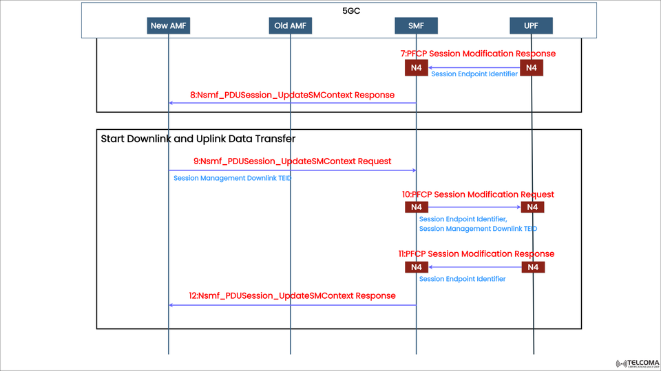
The diagram shows how the SMF works with the AMF and UPF to finalize data setup after the initial registration.
This phase mainly consists of:
Updating the Session Management Context following PFCP configuration.
Kicking off the setup for downlink and uplink paths.
Making sure the data plane is ready.
Step-by-Step Breakdown of Signaling
Step 7: PFCP Session Modification Response
Interface: N4 (UPF ↔ SMF)
Purpose: To acknowledge the session modification requested by the SMF during the earlier setup phase.
Details:
This includes the Session Endpoint Identifier, which confirms the PFCP session update.
It ensures that the UPF is prepared for data transfer.
This step signifies that the UPF has wrapped up the essential configurations (like tunnel parameters and QoS rules) for managing user traffic.
Step 8: Ns mf ext {}PDU Session ext {}Update SM Context Response
Interface: N11 (SMF → New AMF)
Purpose: To let the SMF confirm that it has updated the Session Management Context with the new AMF.
Outcome:
The AMF now has the latest SM context linked to the UE’s PDU session.
All network components are in sync with the updated session parameters.
This response wraps up the SM context update, allowing the AMF to handle mobility and policy signaling efficiently.
Kicking Off Downlink and Uplink Data Transfer
Once the SMF and AMF sync is done, the network can activate both uplink and downlink data flows. This ensures that the UE can send and receive data packets.
Step 9: Ns mf ext {}PDU Session ext {}Update SM Context Request
Interface: N11 (New AMF → SMF)
Purpose: To inform the SMF about updating the SM context to start downlink data transfer.
Parameters:
Session Management Downlink TEID
Session Endpoint Identifier
This step indicates that the UE and AMF are ready for active communication, prompting the SMF to begin the data path setup in the user plane.
Step 10: PFCP Session Modification Request
Interface: N4 (SMF → UPF)
Purpose: The SMF instructs the UPF to set up the downlink data path.
Key Fields:
Session Endpoint Identifier
Session Management Downlink TEID
The PFCP Session Modification Request is really important here, as it directs the UPF to establish or modify the packet forwarding rules, ensuring the downlink traffic routes correctly toward the UE.
Step 11: PFCP Session Modification Response
Interface: N4 (UPF → SMF)
Purpose: To confirm that the PFCP modification for downlink and uplink data flow was successful.
Contents:
Session Endpoint Identifier that confirms completion.
This message lets you know that the UPF has configured all needed parameters and is set to forward both uplink and downlink traffic between the UE and the data network.
Step 12: Ns mf ext {}PDU Session ext {}Update SM Context Response
Interface: N11 (SMF → New AMF)
Purpose: The SMF confirms the completion of the downlink setup and its readiness for data transfer.
Outcome:
The AMF can now notify the UE that its session is fully active.
Both uplink and downlink flows are up and running.
This final step successfully completes the setup for user data transmission in the 5G standalone environment.
Interfaces and Protocols at Play
InterfaceBetweenProtocolPurposeN11AMF ↔ SMF Service-Based Interface (SBI)Session Management signalingN4SMF ↔ UPFPFCP User Plane configuration and tunnel setup
N11 (Service-Based Interface): Handles control plane communication, allowing for SM context updates.
N4 (PFCP-based): Sets up data forwarding rules between SMF and UPF, controlling the activation of the data plane.
Technical Deep Dive: Modifications in PFCP Sessions
The PFCP (Packet Forwarding Control Protocol) messages are crucial for setting up data paths in the 5G core:
PFCP Session Modification Request: Adjusts or updates packet forwarding rules, TEIDs, QoS enforcement, and tunnel parameters.
PFCP Session Modification Response: Confirms the UPF's readiness to manage user data traffic.
These exchanges ensure that the control plane (SMF) and user plane (UPF) are perfectly aligned for smooth, policy-driven traffic flow.
Importance of TEIDs and Session Endpoint Identifiers
Parameter Definition Purpose TEID (Tunnel Endpoint Identifier)Identifier for GTP-U tunnels Separates traffic flows for specific PDU sessions Session Endpoint Identifier Unique ID in PFCP session Links control messages to specific data sessions
These identifiers make sure that packets for each UE’s PDU session are routed correctly through the UPF and properly associated with the control session handled by the SMF.
Why This Phase Matters in 5G SA Networks
This second phase of SMF interaction is key because it moves the network from session configuration to actual data transmission.
Key advantages include:
Continuous mobility: Guarantees UE data flow after AMF reallocation.
Low latency: Optimized data routing through dynamically selected UPFs.
Effective policy enforcement: Real-time sync with PCF and UDM policies.
Dynamic scalability: Handles multiple PDU sessions for a variety of service types (eMBB, URLLC, mMTC).
Message Flow Summary
Step Message/ActionDirectionPurpose7PFCP Session Modification Response UPF → SMF Acknowledge the session update8Nsmf ext {}PDU Session ext{}Update SM Context Response SMF → New AMF Confirm the context update9Nsmf ext{}PDU Session ext {}Update SM Context Request New AMF → SMF Start downlink data setup10PFCP Session Modification Request SMF → UPF Set up the downlink path11PFCP Session Modification Response UPF → SMF Confirm PFCP modification12Nsmf ext{}PDU Session ext {}Update SM Context Response SMF → New AMF Finalize downlink/uplink setup
Wrap-Up
The SMF interactions during 5G standalone access registration are crucial for creating effective data transfer channels within the 5G Core network.
In this stage, the SMF:
Completes session updates between the AMF and UPF,
Sets up uplink and downlink paths, and
Makes sure data flows seamlessly for user sessions.
These interactions highlight the intelligent control that characterizes 5G’s framework — dynamically connecting users, services, and data with precision and speed. For telecom engineers, grasping these message flows is fundamental to mastering 5G Core optimization and network orchestration.