
5G Standalone Access Registration: Step-by-Step Guide to UE and gNB RRC Connection Setup

Understanding 5G Standalone Access Registration and RRC Connection Setup
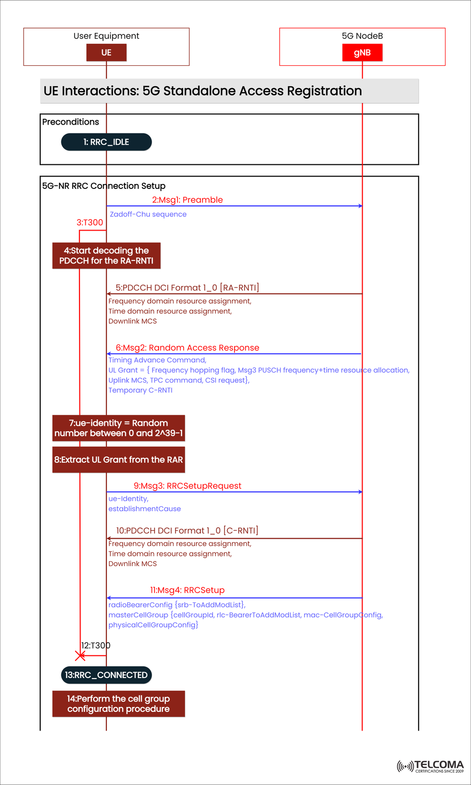
In the 5G Standalone (SA) design, when a User Equipment (UE) first connects to the 5G Core (5GC), it goes through a crucial step known as Access Registration.
The diagram provided shows how this works, especially highlighting the interaction between the UE and gNB, which details the establishment of the RRC (Radio Resource Control) connection via the 5G NR Random Access (RA) process.
This article breaks down each phase depicted in the diagram — from the RRC_IDLE state to the RRC_CONNECTED state — explaining the messages sent, timers involved, and the reasoning behind each interaction.
The Role of Access Registration in 5G SA
Access registration acts like the first handshake between a device (UE) and the network (gNB). It makes sure the UE can:
Sync up with the cell
Get timing and uplink grants
Set up signaling radio bearers
Move from RRC_IDLE to RRC_CONNECTED
This step happens before the NAS-level registration with the 5G Core and mostly involves layers like PHY, MAC, and RRC.
Preconditions: UE in RRC_IDLE
Before kicking things off, the UE is sitting in the RRC_IDLE state. In this state:
The UE listens in on SS/PBCH and System Information Blocks (SIBs) to figure out the cell and its configuration.
It picks a suitable cell and gets ready for the Random Access Procedure (RAP).
The goal for the UE is to set up an RRC connection for:
Initial access
Handover from another cell
Reestablishment after a failure
5G-NR RRC Connection Setup: Step-by-Step
Step 2: Msg1 – Preamble Transmission
The UE kicks off the Random Access Procedure by sending Msg1: Preamble to the gNB on the PRACH (Physical Random Access Channel).
This preamble is created using a Zadoff-Chu sequence, which is good for correlation and detection.
It signals the UE’s request to connect to the network.
At this moment, Timer T300 starts to keep an eye on how long it takes for the RAR message to come back.
Step 4: Start Decoding the PDCCH for the RA-RNTI
The gNB allocates some resources and schedules the UE’s response on the PDCCH (Physical Downlink Control Channel), using an RA-RNTI (Random Access-RNTI) identifier.
The UE begins decoding the PDCCH messages to pick up on the PDCCH DCI Format 1_0 [RA-RNTI], which has:
Frequency domain resource assignment
Time domain resource assignment
Downlink Modulation and Coding Scheme (MCS)
Step 6: Msg2 – Random Access Response (RAR)
Once the gNB gets the preamble, it replies with a Random Access Response (Msg2) on the PDSCH.
This message contains:
Timing Advance Command – which adjusts the UE’s uplink timing to sync up transmissions
Uplink Grant – specifying frequency, time, and power control parameters
Temporary C-RNTI – a temporary ID for the UE during this process
The Uplink Grant might also include:
Frequency hopping flags
Msg3 PUSCH resource allocation
CSI (Channel State Information) request
Step 7: UE Identity Generation
At this point, the UE generates a temporary UE identity, which is just a random number between 0 and 2^39–1.
This number will later be part of the RRCSetupRequest to identify the UE.
Step 8: Extract UL Grant from RAR
The UE pulls out the uplink grant info from the RAR message to figure out:
Which resources to use for sending Msg3
How to encode and time its transmission
Step 9: Msg3 – RRC Setup Request
The UE sends the RRC Setup Request (Msg3) to the gNB, using the uplink resources it got in Msg2.
The RRC Setup Request includes:
UE identity (Temporary C-RNTI or random ID)
Establishment Cause (like Mobile-Originated Signaling, Emergency, or Data Transfer)
This step shifts the process from Random Access (RA) to RRC-level signaling.
Step 10: PDCCH DCI Format 1_0 [C-RNTI]
The gNB answers the UE’s request by scheduling the RRCSetup message with a PDCCH DCI Format 1_0 [C-RNTI], which includes:
Frequency domain resource assignment
Time domain resource assignment
Downlink MCS
The gNB now pairs the UE’s temporary ID with a C-RNTI (Cell RNTI), giving it a unique ID within that cell.
Step 11: Msg4 – RRCSetup
The RRC Setup (Msg4) message from the gNB wraps up the RRC connection setup. It carries:
radio Bearer Config: This defines the SRB (Signaling Radio Bearer) setup (usually SRB1).
master Cell Group: This contains parameters for MAC, RLC, and PHY settings.
physical Cell Group Config: This offers cell-specific configurations.
Once the UE receives Msg4, it implements these configurations, sets up the signaling bearer, and moves into an active RRC state.
Step 12: T300 Expiry (Handled)
If Msg4 doesn’t reach the UE before the T300 timer runs out, the UE will consider the attempt a fail and restart the random access process. But in a successful case, Msg4 is received and decoded correctly before the timer expires.
Step 13: Transition to RRC_CONNECTED
After successfully finishing the RRCSetup, the UE shifts from RRC_IDLE to RRC_CONNECTED.
In this state:
The UE can send NAS messages to the AMF.
The gNB keeps the UE context.
Dedicated radio bearers (DRBs) can be set up later for user data.
This means the UE now has a dedicated signaling connection with the network.
Step 14: Perform Cell Group Configuration Procedure
Once the UE hits RRC_CONNECTED, it goes through cell group configuration, applying settings from masterCellGroup and physicalCellGroupConfig.
This ensures:
Proper sync of uplink and downlink channels.
Setup of MAC and RLC entities.
Readiness for the following NAS registration and data setup procedures.
Technical Insights
RRC States:
RRC_IDLE: UE listens for broadcast messages and carries out random access.
RRC_CONNECTED: UE has a signaling connection established with gNB.
RNTI Types:
RA-RNTI: Used during random access.
C-RNTI: Assigned after successful RRC setup.
Timers:
T300: Monitors the RRC setup process; if it runs out, access is retried.
PDCCH DCI Formats:
Format 1_0 defines downlink scheduling and resource assignments.
Why RRC Connection Setup Matters
The RRC connection setup is essential for enabling:
NAS signaling for registration, authentication, and session management.
Security configuration (activating integrity and ciphering).
User-plane establishment for PDU sessions.
Without a proper RRC connection, the UE won’t be able to interact with the core network.
Conclusion
The 5G NR RRC Connection Setup lays the groundwork for UE–network communication in the 5G Standalone setup. Through a structured sequence — from Msg1 to Msg4, backed by PDCCH scheduling and RNTI management — the UE moves from RRC_IDLE to RRC_CONNECTED, primed for NAS registration and service setup.
For professionals in telecom, grasping this flow is key to troubleshooting access issues, optimizing random access parameters, and ensuring effective call setup performance in 5G networks.