
5G Standalone Access: RRC Connection Setup Procedure Explained Step-by-Step

Understanding the 5G Standalone Access: RRC Connection Setup Process
Once the Random Access Procedure (Msg1–Msg2) wraps up in a 5G Standalone (SA) network, the next key step is the RRC Connection Setup Procedure. This step is crucial as it allows the User Equipment (UE) to set up a Radio Resource Control (RRC) connection with the gNB (5G NodeB), moving from an RRC_IDLE state to RRC_CONNECTED.
In this post, I'll break down the complete message sequence (Msg3–Msg4) shown in the provided image and explain its significance in the 5G registration process.
What’s RRC Connection Setup?
The RRC Connection Setup is part of the 5G NR (New Radio) Access Stratum procedures. Its main job is to facilitate control signaling, security, and configuration parameters between the UE and the gNB, which are essential for interacting with the 5G Core (5GC).
To put it simply, this part of the process establishes a dedicated signaling connection that enables the following higher-layer operations:
Registration with the 5GC
Setting up PDU sessions
Security configurations
Creation of radio bearers
Before Starting the RRC Setup
Before diving into the RRC setup, the following tasks from the earlier Random Access Procedure need to have taken place:
The UE sent a preamble (Msg1) via the PRACH.
The gNB responded with a Random Access Response (Msg2), which included timing advance, UL grant, and a temporary C-RNTI.
Now, the UE is set to send Msg3 (RRCSetupRequest) to kick off the RRC connection.
Overview of Message Flow
The RRC setup phase includes exchanges of Msg3 and Msg4 between the UE and the gNB:
Step | Message Name | Direction | Description
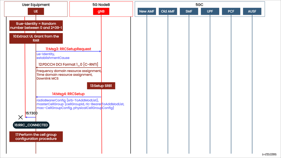
9–10 | UE Identity Generation & UL Grant Extraction | UE Internal Steps | The UE prepares to send RRC Setup Request
11 | Msg3: RRC Setup Request | UE → gNB | UE requests RRC connection with identity and reason for connection
12 | PDCCH DCI Format 1_0 [C-RNTI] | gNB → UE | Schedules downlink resources for Msg4
13 | Setup SRB1 | gNB Internal | Configures the signaling radio bearer (SRB1)
14 | Msg4: RRC Setup | gNB → UE | Sends radio bearer and cell group configuration
15–16 | Timer T300 Stop & RRC_CONNECTED | UE State Change | The UE enters RRC_CONNECTED state
17 | Cell Group Configuration Procedure | UE Internal | UE finalizes configuration for communication
Detailed Breakdown of the 5G RRC Setup Procedure
Let’s walk through each labeled step outlined in the image.
Step 9: UE Identity Generation
The UE creates a temporary identity, which is a random number ranging from 0 to 2^39–1.
This random UE identity helps maintain anonymity before authentication.
It’s included in the RRCSetupRequest message, allowing the gNB to uniquely identify the UE within the cell.
Step 10: Getting Uplink Grant from RAR
The UE pulls the Uplink (UL) Grant parameters from the Random Access Response (RAR) it received earlier.
This UL grant dictates the frequency, timing, and modulation settings to send Msg3.
Step 11: Msg3 – RRC Setup Request
Now, the UE sends the RRC Setup Request to the gNB using the allocated UL resources.
This message comprises:
UE Identity: The random number generated in Step 9.
Establishment Cause: It indicates why the connection is being made (e.g., Mobile Originated Data, Emergency, Registration, or Signaling).
The purpose of this message is twofold:
To inform the gNB that the UE wishes to establish an RRC connection.
To provide necessary identification info to kick off resource allocation.
Step 12: PDCCH DCI Format 1_0 [C-RNTI]
After receiving the RRCSetupRequest, the gNB allocates downlink resources for its response.
It uses DCI Format 1_0, aimed at the C-RNTI (Cell Radio Network Temporary Identifier) assigned earlier.
The DCI message includes:
Frequency domain resource assignment
Time domain resource assignment
Downlink MCS (Modulation and Coding Scheme)
This ensures the UE knows where to receive the next downlink message, Msg4.
Step 13: Establishing SRB1 (Signaling Radio Bearer 1)
Before sending Msg4, the gNB sets up SRB1 — a logical channel dedicated to RRC and NAS (Non-Access Stratum) signaling.
SRB0 was utilized for Msg3 transmission (common signaling).
After establishing the RRC connection, SRB1 takes over for dedicated signaling between UE and gNB.
This signifies a shift from common to dedicated signaling resources.
Step 14: Msg4 – RRCSetup
The gNB sends Msg4: RRCSetup to the UE. This is a key message in the initial access process.
It includes configuration info needed to manage the radio link:
radio Bearer Config:
srb-To Add Mod List: Specifies details for SRB1.
master Cell Group:
cell Group Id: Identifies the main cell group.
rlc-Bearer To Add Mo dList: Configures RLC bearers.
mac-Cell Group Config, physical Cell Group Config: Define MAC and PHY layer parameters.
The aim here is to set up UE-side resources for the new connection and shift the UE to an active, synchronized communication state.
Step 15: Timer T300 Stops
The T300 timer, which began when the UE sent the RRC Setup Request, halts once Msg4 is received.
If the timer had run out before Msg4 came in, the UE would have to retry the procedure.
Step 16: UE Moves to RRC_CONNECTED
At this stage, the RRC connection is established, allowing the UE to shift from RRC_IDLE to RRC_CONNECTED.
In this state, the UE:
Has a dedicated RRC connection.
Can send and receive both user data and control info.
Begins higher-layer signaling with the 5GC via the gNB.
Step 17: Cell Group Configuration Procedure
The final stage involves configuring the cell group.
The UE applies the parameters received from Msg4 to adjust its MAC, RLC, and PHY layers.
This ensures the UE aligns fully with the gNB’s configuration.
Now, the UE is set to handle registration, authentication, and PDU session establishment with the 5G Core Network (AMF, SMF, UPF, PCF, AUSF).
Why RRC Connection Setup Matters in 5G
The RRC setup process is vital because it:
Establishes the first dedicated communication channel between the UE and the network.
Kicks off security and QoS setups for subsequent signaling.
Enables mobility management and handover capabilities.
Lays the groundwork for data session establishment and 5G service delivery.
Common Challenges in RRC Setup
Despite being a standardized process, several real-world challenges can arise:
Preamble Collision: When two UEs send the same preambles, it can delay Msg3 scheduling.
DCI Scheduling Errors: If DCI resources aren’t decoded properly, Msg4 could be overlooked.
Weak Signal Conditions: Low SINR can lead to RRC Setup failures.
Timing Issues: Incorrect timing adjustments can result in out-of-sync transmissions.
Network optimization tools monitor RRC setup success rates as a key performance indicator for network performance.
Connecting with the 5G Core (5GC)
Once the UE is in RRC_CONNECTED, the gNB can communicate with the Access and Mobility Management Function (AMF) in the 5GC for:
Sending registration requests
Setting up security contexts
Forwarding NAS signaling
Other core components like SMF, UPF, PCF, and AUSF will get involved as the UE establishes user-plane connectivity and data sessions.
Summary Table: Key Parameters in RRC Setup
Parameter | Description
UE Identity | Random temporary ID (0 to 2^39–1)
Establishment Cause | Reason for connection (e.g., registration, data)
DCI Format 1_0 | Downlink control information format
SRB1 | Dedicated signaling bearer for RRC/NAS
C-RNTI | Temporary UE identifier during setup
Timer T300 | Wait timer for Msg4 reception
RRC_CONNECTED | UE’s active communication state
Wrapping Up
The RRC Connection Setup Procedure in 5G Standalone networks serves as the crucial link between the initial random access and full network registration.
Through the exchanges of Msg3 (RRC Setup Request) and Msg4 (RRC Setup), the UE transitions from RRC_IDLE to RRC_CONNECTED, paving the way for dedicated signaling, security, and resource control.
For professionals in telecom, grasping this procedure is essential for analyzing RRC KPIs, improving access performance, and resolving 5G SA connection challenges.