
5G System Service-Based Architecture Explained: Core Network Functions and Interfaces

Getting to Grips with the 5G Service-Based Architecture (SBA)
The 5G System Service-Based Architecture (SBA) represents a significant departure from the traditional 4G EPC (Evolved Packet Core), leaning towards a cloud-native, modular, and service-oriented model.
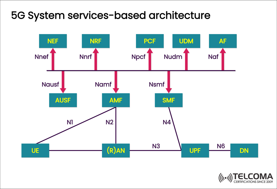
In the architecture shown, various Network Functions (NFs) interact using standardized service-based interfaces (SBI). This setup provides the flexibility, scalability, and efficiency needed for contemporary applications such as IoT, ultra-reliable low-latency communication (URLLC), and enhanced mobile broadband (eMBB).
What’s 5G Service-Based Architecture All About?
In 4G LTE, different network elements communicated via point-to-point interfaces (like S1, S5, S11). In contrast, 5G rolls out a Service-Based Architecture where each network function offers services to others through standardized APIs (Application Programming Interfaces).
This shift enables:
Easier integration of new services
Cloud-native deployments
Dynamic scaling and load balancing
Improved network efficiency and automation
With the SBA, the 5G Core (5GC) becomes flexible enough to support an array of services and industries—from everyday consumer broadband to industrial IoT.
Key Components of the 5G Service-Based Architecture
The diagram breaks down the main Network Functions (NFs) of the 5G Core into Control Plane (CP) and User Plane (UP) functions. Here’s a closer look:
UE (User Equipment)
The UE refers to the end device, which can be anything from a smartphone to an IoT sensor or vehicle modem.
It connects to the network via the (R)AN (Radio Access Network) through the N1 interface.
(R)AN – Radio Access Network
(R)AN includes gNodeB (for 5G NR) or ng-eNodeB (for LTE-based 5G).
It takes care of radio resource management, handles handover, and sets up initial connections.
Interfaces:
N2: Connects the RAN to the AMF (Access and Mobility Management Function).
N3: Links to the UPF (User Plane Function) for user data traffic.
AMF – Access and Mobility Management Function
The AMF serves as the main control component responsible for:
Managing UE registration and connection setup
Overseeing mobility management (handover, tracking area updates)
Sending session management messages to the SMF
Service interface: Namf
Connected to: UE (N1), (R)AN (N2), SMF (Nsmf), and other control plane NFs like PCF and AUSF.
SMF – Session Management Function
The SMF takes charge of PDU sessions (data sessions) and manages the User Plane Function (UPF). Here’s what it does:
Allocates IP addresses to UEs
Manages traffic routing and QoS
Handles session establishment, modification, and release
Service interface: Nsmf
Connects to: AMF, UPF (N4), PCF, and UDM.
UPF – User Plane Function
The UPF is part of the User Plane, responsible for forwarding user data between the RAN and the Data Network (DN). Its main roles include:
Routing and forwarding packets
Traffic shaping and enforcing QoS
Usage reporting for billing purposes
Connecting to external networks (Internet, enterprise LANs)
Interfaces:
N3: From RAN
N4: From SMF
N6: To Data Network (DN)
UDM – Unified Data Management
The UDM is the 5G counterpart to the HSS (Home Subscriber Server) in 4G, handling and storing subscriber data such as:
User identities and authentication info
Subscription details
Network slice selection and policy data
Service interface: Nudm
Communicates with: AMF, SMF, AUSF, and PCF.
AUSF – Authentication Server Function
The AUSF is responsible for authenticating UEs during registration.
It collaborates with UDM to verify subscriber credentials.
It supports 5G-AKA and EAP-AKA’ authentication methods.
Service interface: Nausf
Connected to: AMF and UDM.
PCF – Policy Control Function
The PCF oversees policy and charging control within the 5G Core.
It provides QoS policy rules to the SMF.
Manages network slicing and sets session priorities.
Ensures users receive the correct QoS based on their subscriptions and services.
Service interface: Npcf
Connected to: AMF, SMF, and UDM.
NRF – Network Repository Function
The NRF acts as the directory service for all Network Functions (NFs).
It maintains a registry of all available services and their locations.
Facilitates service discovery and load balancing among NF instances.
Service interface: Nnrf
Connected to: All NFs for service registration and discovery.
NEF – Network Exposure Function
The NEF allows for secure and controlled exposure of network capabilities to external applications and third-party services.
It provides APIs for developers and enterprise applications.
Supports use cases like IoT service integration and network optimization.
Service interface: Nnef
Connected to: AF, AMF, SMF, and PCF.
AF – Application Function
The AF works with the PCF and NEF to request specific policies or expose services.
It enables:
Application-level QoS requests
Coordination of edge computing
Network analytics for optimization.
Service interface: Naf
Connected to: PCF and NEF.
DN – Data Network
The Data Network (DN) refers to the endpoints where user traffic terminates, whether internal or external, such as:
The Internet
Enterprise intranets
Cloud service platforms
Interface: N6 connects the UPF to the DN.
Key Interfaces in the 5G Service-Based Architecture
The diagram highlights key interfaces that facilitate seamless communication throughout the network:
InterfaceConnectsPurposeN1UE ↔ AMFNAS signaling and registrationN2(R)AN ↔ AMF Control-plane signalingN3(R)AN ↔ UPF User-plane data transferN4SMF ↔ UPF User-plane session controlN6UPF ↔ DN Data network access Nnrf, Npcf, Namf, etc. Between NFs Service-based communication APIs
Advantages of the Service-Based Architecture
The SBA design offers numerous benefits compared to older architectures:
Cloud-Native Flexibility: Enables deployment in containers or microservices, perfect for virtualized and edge environments.
Network Slicing: Grants each service or customer their own dedicated logical network.
Scalability: Functions can scale independently based on demand.
Interoperability: Standardized APIs guarantee compatibility across different vendors.
Automation: Streamlines network orchestration and lifecycle management.
5G SBA Compared to 4G EPC
Aspect4G EPC5G SBA Architecture Type Point-to-point Service-based Core Components MME, SGW, PGWAMF, SMF, UPF Control/User Plane Split Limited Fully separated Scalability Monolithic Cloud-native and modular Network Exposure Limited APIs API-based exposure via NEF Service Flexibility Static Dynamic and programmable
How SBA Fuels Modern 5G Use Cases
Thanks to its adaptable and modular structure, the SBA supports:
Ultra-Reliable Low-Latency Communication (URLLC) for industrial automation.
Enhanced Mobile Broadband (eMBB) for high-speed data services.
Massive IoT (mMTC) connectivity for millions of low-power devices.
Network Slicing for tailored performance levels per service type.
Conclusion
The 5G Service-Based Architecture is truly a transformative leap in mobile network design. By swapping out rigid interfaces for API-driven, service-oriented communication, it sets the stage for innovation and agility in the telecom world.
As illustrated in the diagram, the SBA connects key functions like AMF, SMF, PCF, NRF, and UPF, allowing for smart orchestration and real-time adaptability. This architecture isn’t just the backbone of current 5G networks—it's a roadmap for future-proof, cloud-native communication systems that will pave the way for the 6G era and beyond.