
5G UPF Setup and Security Mode Command Explained: A Complete Call Flow Guide

5G UPF Setup and Security Mode Command: A Simple Guide
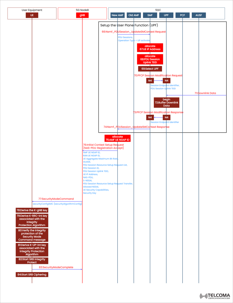
The setup of the 5G User Plane Function (UPF) and the Security Mode Command (SMC) are two key steps that come after the authentication and registration in a 5G Core (5GC) network.
This stage ensures that:
The user plane (the path for data traffic) is correctly established.
Communication between UE (User Equipment) and the network is secured through encryption and integrity checks.
The 5G Core components—AMF, SMF, UPF, PCF, and gNB—are in sync for safe data transmission.
The illustration shows the end-to-end signaling flow including various 5G Core parts and the gNB.
Getting to Know the UPF and SMC Setup
What’s the User Plane Function (UPF)?
The UPF is in charge of forwarding user data packets within the user plane. It handles IP address assignments, enforces Quality of Service (QoS), and manages routing between the UE and external data networks (DNs).
What’s the Security Mode Command (SMC)?
The SMC procedure guarantees that all NAS and RRC signaling between the UE and AMF/gNB is integrity protected and encrypted. This ensures that data remains confidential and authentic.
These steps work together to enable secure data transfer once the UE is fully registered and authenticated.
Step-by-Step Breakdown of the 5G UPF Setup Flow
The sections below go through the setup of the User Plane Function and the Security Mode Command, as depicted in the diagram.
- Setting Up the User Plane Function (UPF)
After registration and authentication, the SMF (Session Management Function) kicks off the UPF setup, making sure that all data paths are configured properly.
Step 66: Nsmf_PDU Session_Update SM Context Request
The SMF sends an Nsmf_PDU Session_Update SM Context Request to the UPF using the N4 interface.
Purpose: To activate the User Plane (UP) for the existing PDU Session.
Contents: Details about the PDU Session, the operation type (UP activate), and context info.
Step 67: Allocate IP Address
The UPF assigns an IP address to the UE.
This IP address serves as the UE’s anchor point for data connectivity within the 5G network, allowing data flows to and from external networks.
Step 68: Allocate Uplink TEID
The UPF provides an Uplink Tunnel Endpoint Identifier (TEID) for GTP-U tunneling between the gNB and UPF.
This identifier uniquely defines each data tunnel, ensuring packets are routed correctly.
Step 69: Select UPF
The SMF picks the suitable UPF instance based on:
Network slice needs
QoS requirements
Proximity
Policy control rules (from PCF)
This choice optimizes performance while keeping latency low.
Step 70: PFCP Session Modification Request
The SMF sends a PFCP Session Modification Request (through the N4 interface) to the UPF to apply the new session parameters:
Session Endpoint Identifier
PDU Session Uplink TEID
This updates the UPF with the necessary user plane configuration.
Step 71: Buffering Downlink Data
The UPF can start buffering downlink packets (from the external data network to the UE) while waiting for the UE to finish its access setup. This way, no data is lost during the session setup process.
Step 72: PFCP Session Modification Response
The UPF responds with a PFCP Session Modification Response, confirming the session context update was successful. Now, both the SMF and UPF are in sync for data transmission.
Step 74: Nsmf_PDU Session_Update SM Context Response
The SMF sends a confirmation back to the AMF via Nsmf_PDU Session_Update SM Context Response, indicating that the user plane setup is now complete.
- UE Context Setup with the AMF and gNB
Once the UPF is ready, the AMF has to establish a radio and signaling context with the gNB so the UE can start encrypted communication.
Step 75: AMF Allocates UE NGAP ID
The AMF gives a unique UE NGAP ID to identify the UE in the NG interface between the gNB and AMF.
This ID is essential for routing NAS messages and handling mobility events.
Step 76: Initial Context Setup Request
The AMF sends an Initial Context Setup Request to the gNB, which contains:
NAS-PDU (Registration Accept message)
AMF UE NGAP ID and RAN UE NGAP ID
UE Aggregate Maximum Bit Rate (AMBR)
Allowed NSSAI (Network Slice Selection Assistance Information)
Security Key and Capabilities
PDU Session Resource Setup Information
This step effectively sets up the radio and core network link for user data transmission.
- Kicking Off the Security Mode Command
After the context setup, the AMF initiates the Security Mode Command (SMC) to start NAS and RRC encryption for secure signaling.
Step 77: Security Mode Command
The AMF sends the Security Mode Command message to the UE through the gNB, containing:
Security algorithm details (SMC)
Options for integrity and ciphering
Now, the UE needs to enable encryption and integrity mechanisms using the shared security keys from earlier.
Steps 78–79: Deriving Security Keys
The UE derives several keys from the base key K_AMF:
K_gNB – for securing communication between UE and gNB
K_RRCint – for RRC integrity protection
K_UPint – for uplink integrity protection
This ensures end-to-end encryption from the UE to the network.
Step 80: Verifying Security Mode Command Integrity
The UE checks the integrity of the received Security Mode Command message using K_RRCint, making sure the message hasn’t been tampered with.
Steps 81–82: Activating Integrity Protection
After verification, the UE turns on:
NAS Integrity Protection for signaling messages
RRC and SRB Integrity Protection for radio messages
Now the gNB and UE have matching security setups.
Step 83: Security Mode Complete
The UE sends a Security Mode Complete message to the AMF, confirming that encryption and integrity protection have been successfully activated.
Step 84: Starting SRB Ciphering
At last, SRB (Signaling Radio Bearer) Ciphering begins. This ensures that all future control plane messages are encrypted for confidentiality.
Benefits of Proper UPF and SMC Configuration
Secure Communication: Stops eavesdropping and tampering on signaling and data.
Optimized Performance: Dynamic UPF choice enhances latency and throughput.
Scalability: Aids flexible routing and slicing across multiple UPFs.
Reliability: Ensures user sessions remain secure, even when mobility events occur.
QoS Enforcement: Policies driven by PCF ensure the right QoS levels for each user session.
Troubleshooting Tips
Common Issues:
UPF Selection Failure: Check SMF–NRF registration and slice mapping.
TEID Mismatch: Look over GTP-U tunnel settings.
Security Mode Rejection: Ensure key derivation and algorithm matching are correct.
NAS Encryption Errors: Make sure K_AMF derivation follows 3GPP TS 33.501 standards.
Conclusion
The 5G UPF Setup and Security Mode Command play a crucial role in moving from registration to secure data transmission.
The UPF is all about efficient user-plane data routing, while the Security Mode Command activates encryption and integrity to protect user traffic.
With the teamwork of AMF, SMF, UPF, PCF, and gNB, the 5G Core strikes a balance between performance optimization and robust security, allowing users to enjoy seamless, high-speed, and secure connectivity.