
Access and Mobility Function Sequence in 5G Core (5GC): Step-by-Step Workflow Explained

Access and Mobility Function Sequence in 5G Core (5GC)
The architecture of the 5G network brings in a service-based, cloud-native core that effectively handles user access, mobility, and data sessions. At the heart of this architecture is the Access and Mobility Function (AMF) sequence. It plays a key role in how user devices (UEs) connect, move, and maintain continuity of service.
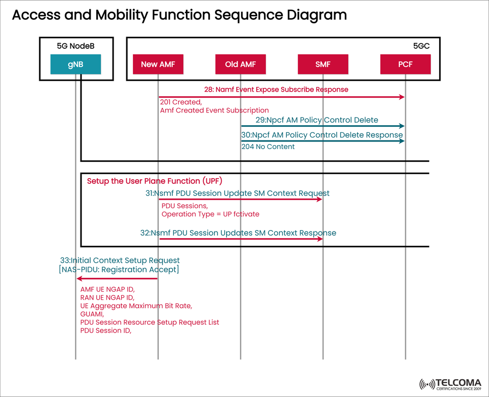
The image attached, titled “Access and Mobility Function Sequence Diagram,” clearly depicts this interaction. It demonstrates how the 5G NodeB (gNB) communicates with various entities within the 5G Core (5GC) like AMF (Access and Mobility Function), SMF (Session Management Function), and PCF (Policy Control Function) during session setups and mobility events.
Let’s break all this down step-by-step so we can grasp what each function does and how this sequence supports smooth mobility management in a 5G network.
Overview: Access and Mobility Management in 5G
In the 5G System (5GS), AMF is crucial for managing user registration, authentication, connection setup, and mobility between base stations.
It collaborates with other core network elements such as:
SMF (Session Management Function) – which takes care of PDU session management and user plane configuration.
PCF (Policy Control Function) – responsible for making policy decisions about mobility and session management.
UPF (User Plane Function) – which handles the forwarding of user data.
gNB (5G NodeB) – manages the radio access link with the UE.
All these components work together to ensure that whenever a user moves, starts a session, or switches networks, the connection stays stable, secure, and compliant with policies.
Understanding the Sequence Diagram
The diagram shows a time-sequenced flow involving five entities:
5G NodeB (gNB)
New AMF
Old AMF
SMF (Session Management Function)
PCF (Policy Control Function)
This process unfolds during a mobility event, typically when a user's device shifts between two AMF regions. The sequence guarantees:
Context information is passed from the old AMF to the new one.
PDU sessions stay active.
Policy rules are updated or removed as needed.
The User Plane Function (UPF) gets set up for new routing.
Step-by-Step Breakdown of the Access and Mobility Sequence
Let’s look more closely at the major steps as illustrated in the diagram.
Step 28: Namf Event Expose Subscribe Response
The New AMF sends an event exposure subscription response to the PCF.
This step ensures that the PCF is now informed about the new AMF managing the UE and will direct future policy decisions accordingly.
The message contains: * 201 Created (HTTP Response) – which indicates that the event subscription was successfully created. * AMF Created Event Subscription details – confirming that the PCF can monitor or respond to changes related to the AMF.
Purpose: This guarantees policy control continuity during AMF reallocation. When a UE transitions to a new AMF region, the PCF needs to be updated to keep policy consistency intact.
Step 29: Npcf AM Policy Control Delete
The New AMF requests that the PCF delete old policy associations tied to the Old AMF. * This is done via the Npcf
_AMPolicy Control_Delete request.
Purpose: This action prevents any policy conflicts and ensures that only the active AMF manages mobility and policy decisions for the current UE.
Step 30: Npcf AM Policy Control Delete Response
The PCF responds with a 204 No Content, confirming that the old AM policy control session has been deleted successfully.
Outcome: The PCF now recognizes just the New AMF as the valid control point for managing the UE’s mobility.
Setting Up the User Plane Function (UPF)
Once the AMF reassignment and policy control cleanup is finished, the next significant step is establishing or updating the User Plane (UP). This part is shown as Setup the User Plane Function (UPF) in the diagram.
Step 31: Nsmf PDU Session Update SM Context Request
The New AMF sends an update request to the SMF. * The message includes: * PDU Sessions * Operation Type = UP Activate
This tells the SMF to reconfigure or activate the User Plane for ongoing PDU sessions, ensuring the UE continues receiving data without any interruptions.
Purpose: This updates the session management context so the UPF can route data through the correct AMF and access point.
Step 32: Nsmf PDU Session Update SM Context Response
The SMF replies to the New AMF, confirming that the PDU session context has been successfully updated.
This confirmation includes details about:
The updated UPF connection.
Session parameters like QoS flows, tunnels, and bearer mapping.
Outcome: A new user plane path is established, allowing active data sessions to continue even as the UE shifts between AMFs.
Step 33: Initial Context Setup Request
After updating the session and user plane, the New AMF sends an Initial Context Setup Request to the gNB. This message includes the NAS-PDU: Registration Accept, marking the successful completion of the registration and mobility management process.
Key parameters included in this message:
AMF UE NGAP ID
RAN UE NGAP ID
UE Aggregate Maximum Bit Rate
GUAMI (Globally Unique AMF Identifier)
PDU Session Resource Setup Request List
PDU Session ID
Purpose: This step re-establishes the UE’s radio connection context with the new AMF. The gNB now utilizes updated session parameters and identifiers to maintain seamless service continuity.
Roles of Key 5G Core Components
Here’s a quick overview of the roles each component plays in this sequence:
Component Full Form Role in the Sequence gNB Next-Generation Node B Manages the radio interface and UE connections New AMF Access and Mobility Management Function Takes over mobility control and registration Old AMF Access and Mobility Management Function Releases old session and policy control SMF Session Management Function Updates PDU session and user plane path PCF Policy Control Function Manages and deletes outdated policy associations UPF User Plane Function Handles user data routing and forwarding
Technical Significance of the Process
The sequence outlined in the diagram highlights AMF reallocation and PDU session continuity—two crucial elements for 5G mobility management.
It guarantees:
Seamless UE mobility across AMF regions.
Consistent policy enforcement by PCF.
Minimal latency and zero data loss during handovers.
Dynamic session updates through SMF and UPF coordination.
This process takes advantage of service-based interfaces (SBI) using HTTP/2 and RESTful APIs, offering much more flexibility, scalability, and modularity compared to LTE’s point-to-point signaling.
Key Messages Explained
Message Name Purpose Protocol Used Namf_Event Expose_Subscribe Subscribes PCF to AMF events Service-Based Interface (SBI)Npcf_AM Policy Control_Delete Removes old policy associations HTTP-based SBI Nsmf_PDU Session_Update SM Context Updates session and user plane SBI via HTTP/2Initial Context Setup Request Sets up radio and session parameters NGAP (over SCTP)
Every message serves a distinct function in transitioning control from one AMF to another while keeping the UE’s session uninterrupted.
Practical Example: UE Mobility Scenario
Picture a UE moving from one region (served by AMF-A) to another (served by AMF-B). Here’s how the sequence ensures a smooth transition:
The UE’s registration context shifts from Old AMF to New AMF.
PCF updates its policies, discarding old bindings.
SMF reconfigures the PDU session to route data through a new UPF.
gNB receives updated registration and PDU session details.
The UE keeps communicating seamlessly without dropping the session.
This AMF relocation process is vital for inter-AMF handovers, mobility across network slices, or multi-PLMN scenarios.
Conclusion
The Access and Mobility Function Sequence Diagram demonstrates how the 5G Core (5GC) effectively manages mobility and session continuity through AMF, SMF, PCF, and UPF interactions.
By utilizing service-based interfaces (SBI) and HTTP-based communication, 5G networks achieve enhanced flexibility, quicker scalability, and better reliability in mobility management than the previous 4G EPC systems.