
CCE Formation in LTE PDCCH: Understanding REs, REGs, and Control Channel Design

In Long-Term Evolution (LTE) networks, the Physical Downlink Control Channel (PDCCH) plays a crucial role in transmitting control information between the base station (eNodeB) and User Equipment (UE). This channel is responsible for sending messages that include scheduling grants, resource allocations, and commands for Hybrid Automatic Repeat Request (HARQ).
At the core of the PDCCH is the Control Channel Element (CCE), which serves as the basic unit for transmitting control information. So, how exactly is a CCE put together? It involves grouping Resource Elements (REs) into Resource Element Groups (REGs), and then combining those REGs into CCEs.
The image uploaded illustrates this process clearly. In this blog, we’ll dive into the details of CCE formation, its role in the LTE architecture, and why it's essential for effective and reliable wireless communication.
Understanding the Building Blocks
- Resource Element (RE)
This is the smallest unit in LTE resource allocation.
It represents one subcarrier over a single OFDM symbol.
It can carry reference signals, control info, or user data.
- Reference Signals (CRS)
These are specialized REs used for channel estimation.
They’re reserved, so you can’t use them for data or control information.
The diagram shows these in blue.
- Resource Element Group (REG)
A REG consists of 4 consecutive REs.
This forms the smallest grouping of REs.
With some REs reserved for CRS, you end up with 4 usable REs in each REG.
- Control Channel Element (CCE)
A CCE is created by combining 9 REGs.
Since each REG has 4 REs, one CCE equals 36 REs.
This configuration ensures effective and adaptable control info mapping.
CCE Formation in LTE PDCCH
The CCE formation process is systematic:
Step 1: Start with REs - REs are spread out over time (OFDM symbols) and frequency (subcarriers). Some REs are set aside for CRS, which means only the remaining REs are up for grabs.
Step 2: Form REGs - Group 4 REs together to create one REG. Each REG is the smallest chunk of usable control channel resources.
Step 3: Bundle REGs into CCEs - 9 REGs come together to form one CCE, so a single CCE contains 36 usable REs.
This hierarchy—RE → REG → CCE—makes sure the LTE PDCCH remains efficient and adaptable to different channel conditions.
Why is CCE Formation Important?
CCE formation isn’t just about structure; it’s crucial for LTE signaling performance.
Error Protection: By grouping REs into REGs and then into CCEs, redundancy is ensured, leading to strong error correction.
Flexible Aggregation: You can combine multiple CCEs to send larger control messages.
Efficient Resource Allocation: This organization lets LTE use its control channels optimally without wasting bandwidth.
Scalability: Different users may need various numbers of CCEs based on their channel quality.
CCE Aggregation Levels
The LTE standard has different aggregation levels to adjust control signaling based on channel conditions:
Aggregation Level 1 → 1 CCE
Aggregation Level 2 → 2 CCEs
Aggregation Level 4 → 4 CCEs
Aggregation Level 8 → 8 CCEs
How it works:
If a UE enjoys good channel quality, it might only need 1 CCE for control info.
In contrast, if a UE is on the cell edge with weaker signals, it'll get multiple CCEs for better reliability.
This adaptive strategy ensures strong signaling across various conditions.
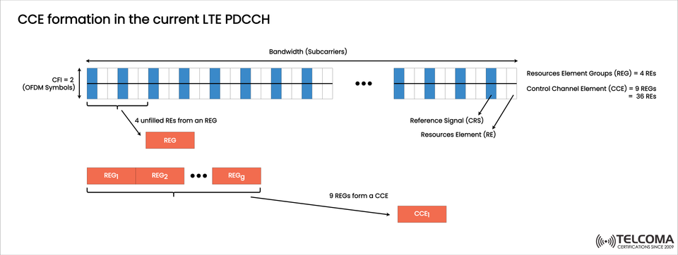
Example Walkthrough from the Image
Let’s break down the diagram step by step:
Bandwidth and Symbols - The top row shows bandwidth (subcarriers) on the X-axis and OFDM symbols on the Y-axis. Here, the Control Format Indicator (CFI) is set to 2, which means two OFDM symbols are designated for control.
Reference Signals (CRS) - The blue-shaded REs are reserved for CRS and can’t be used for control.
REG Formation - Four unfilled REs (shown as white blocks) come together to form one REG.
CCE Formation - Nine REGs are bundled to create a Control Channel Element (CCE), so you get CCE = 9 REGs = 36 REs.
This hierarchy forms the backbone of LTE’s PDCCH signaling.
Applications in LTE PDCCH
The formed CCEs are vital for mapping important control messages:
Downlink Control Information (DCI): Scheduling grants for downlink and uplink.
HARQ Information: ACK/NACK messages for retransmissions.
Power Control Commands: Adjustments for uplink power.
Resource Assignments: Distributing physical resources to UEs.
Without effective CCE formation, LTE control signaling could face higher error rates and less flexibility.
Advantages of the CCE-Based Design
Robustness: Built-in redundancy ensures reliable transmission even in noisy environments.
Flexibility: Supports various aggregation levels for different user conditions.
Scalability: Capable of handling both small and large control messages.
Efficiency: Optimizes the usage of OFDM resources by excluding CRS.
Comparative Table: RE, REG, and CCE
Unit Definition Size Role Resource Element (RE)Smallest LTE unit (1 subcarrier × 1 symbol)1 RE Carries data, control, or reference signals Resource Element Group (REG)Group of 4 REs (excluding CRS)4 REs Smallest control resource group Control Channel Element (CCE)Group of 9 REGs36 REs Fundamental unit of PDCCH control signaling
Challenges in CCE Formation
While CCE formation is efficient, it also comes with its challenges:
PDCCH Bottleneck - Limited control resources can lead to congestion, particularly in crowded networks.
High Aggregation Demand - Users on the edge require more CCEs, which can reduce availability for others.
Interference Sensitivity - Even with its robustness, interference can still impair PDCCH decoding.
Future Outlook: Transition to 5G NR
Though LTE heavily relies on CCE formation for PDCCH, 5G New Radio (NR) introduces a more flexible Control Resource Set (CORESET) concept.
Rather than fixed CCEs, 5G allows for dynamic control resource allocation, offering greater flexibility and better adaptation to various conditions.
Still, the core principle of grouping REs into REGs and then into control units remains the same.
Conclusion
The CCE formation process in LTE PDCCH—going from REs to REGs to CCEs—is fundamental to LTE’s control channel design. It guarantees that important signaling information is transmitted reliably, efficiently, and adaptively across different network conditions.
By structuring resources into these hierarchical units, LTE strikes a balance between robustness and adaptability. And while 5G introduces new mechanisms, the concepts laid out in LTE continue to influence modern wireless communication.
For those in telecommunications, grasping CCE formation is key for mastering LTE optimization, troubleshooting, and the transition to 5G systems.