
Cluster Formation in Multiple FT Scenario: How RDs and FTs Enable Efficient Connectivity

Introduction
Today’s telecom and wireless networks are increasingly shifting towards distributed and intelligent frameworks to keep up with the rising demand for connectivity, scalability, and reliability. One key approach to this is creating clusters in various FT (Fusion Terminal) scenarios, where groups of Relay Devices (RDs) come together, communicating through Fusion Terminals (FTs) to achieve smooth data exchange and Internet access.
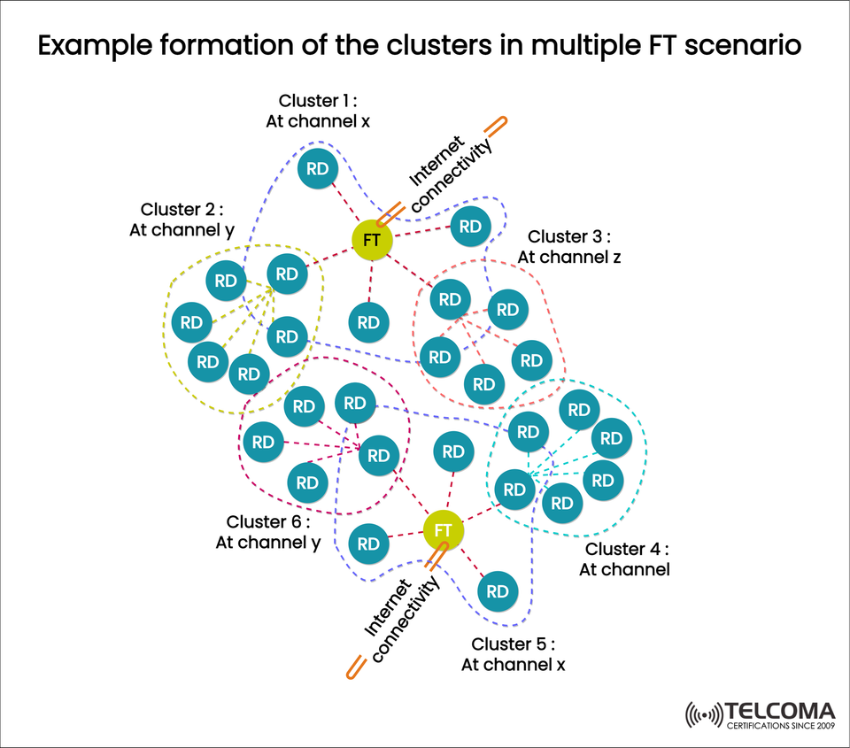
This clustering technique is particularly popular in wireless sensor networks, IoT ecosystems, and cutting-edge telecom setups. The diagram included shows how several clusters are formed, each assigned to a specific channel (like x, y, z, etc.), and illustrates how FTs connect these clusters to the Internet or other external networks.
Key Components in the Cluster Formation
To really grasp the multi-FT scenario, let’s dive into the components highlighted in the diagram.
- Relay Devices (RDs)
Relay Devices serve as the core nodes within each cluster. Their main roles include:
Sending data between end devices and the Fusion Terminal (FT).
Taking part in multi-hop communication to widen coverage.
Helping with load balancing by sharing traffic across the network.
Functioning within particular frequency channels to minimize interference.
These devices effectively create the “mesh” that ensures communication is both reliable and scalable.
- Fusion Terminals (FTs)
Fusion Terminals serve as the heads of the cluster or gateways connecting various RDs to broader networks.
Functions of FT:
Provide Internet access to the cluster.
Collect data from multiple RDs.
Manage channel allocation and synchronization.
Facilitate communication between clusters by connecting across different channels.
In the diagram, you’ll see two FTs, each linking up different groups of clusters.
- Clusters
A cluster consists of a group of RDs that communicate on the same channel, all managed by an FT.
Cluster 1 (Channel X): Has several RDs connected to the FT.
Cluster 2 (Channel Y): Works on a separate frequency to avoid interference.
Cluster 3 (Channel Z): Shows how another distinct channel is used.
Clusters 4, 5, and 6: More examples of how clusters can operate alongside each other, each maintaining order through channel allocation.
This clustering approach helps reduce interference, makes resource management simpler, and boosts scalability.
- Channels (X, Y, Z)
Assigning channels is crucial in multi-FT scenarios. Each cluster works on its own channel to prevent interference, allowing simultaneous transmissions without any clashes.
Channel X: Shared by Cluster 1 and Cluster 5.
Channel Y: Designated for Cluster 2 and Cluster 6.
Channel Z: Specifically for Cluster 3.
Channel reuse is an option if clusters are spaced out enough to avoid interference.
- Internet Connectivity
Every FT links up to the Internet, acting as a bridge between local clusters and global networks. This ensures:
Access from afar for IoT and telecom applications.
Synchronization across nodes that are spread out geographically.
Cloud-based data storage and analytics.
Working of Multiple FT Cluster Formation
The process of creating clusters in a multi-FT setup can be outlined in stages:
Cluster Initialization
RDs come together into clusters based on channel assignments and their closeness to one another.
Each cluster either picks or connects with an FT.
Channel Assignment
Different clusters are assigned separate channels (X, Y, Z, etc.).
If positioned far enough apart, channels can be reused by more distant clusters.
Communication Within Clusters
RDs talk to one another and relay data to the FT.
This intra-cluster communication builds a strong mesh network.
Inter-Cluster Coordination
FTs function as intermediaries between clusters, enabling data transfer across different channels.
This lightens the load on individual RDs for communication between clusters.
Internet Access
FTs connect to outside networks, allowing real-time interaction with cloud applications, OSS/BSS systems, or other services.
Benefits of Cluster Formation in Multi-FT Scenarios
Opting for this architecture brings several key advantages:
Scalability: Clusters can expand without putting too much strain on a single FT or channel.
Interference Reduction: Channel separation helps dodge packet collisions.
Energy Efficiency: RDs only communicate within their own cluster, which saves power.
Resilience: Multiple FTs add redundancy—if one fails, another can step in.
Optimized Bandwidth Usage: Smart use of frequency channels cuts down congestion.
Internet Integration: FTs serve as high-capacity gatekeepers, linking local clusters to the global framework.
Use Cases in Telecom and Wireless Networks
This cluster-based layout is incredibly relevant in today’s communication systems:
5G and Beyond: Supports distributed architectures and small-cell deployments.
IoT Ecosystems: Perfect for managing smart city devices, sensors, and actuators.
Rural Connectivity: Multi-FT clustering is great for extending Internet services to underserved regions.
Enterprise Networks: Allows for scalability in private IoT or industrial wireless setups.
Disaster Recovery: The resilient design means clusters can keep working even if parts of the network go down.
Comparison: Single FT vs. Multiple FT Scenarios
Aspect Single FT Multiple FTS ca lability Limited to the capacity of one FTD is tribute d load across several FTs Redundancy Single point of failure High resilience due to redundancy Channel Utilization Limited flexibility Multiple channels lessen interference Performance Possible bottlenecks Optimized bandwidth allocation Coverage Constrained by FT’s range Wider coverage across regions
Challenges in Multi-FT Cluster Formation
Even with its benefits, this architecture comes with its own set of challenges:
Channel Coordination: Needs smart algorithms to prevent overlaps.
Synchronization: Keeping time across multiple clusters can be tricky.
Management Overhead: More FTs mean increased control and monitoring demands.
Security: More gateways create additional potential targets for attacks.
These hurdles can be tackled with AI-driven orchestration, secure tunneling, and solid policy enforcement.
Conclusion
The formation of clusters in multiple FT scenarios shows how modern telecom and wireless networks can achieve scalability, resilience, and efficiency. By organizing RDs into clusters, assigning distinct channels, and using FTs as gateways, networks are equipped to manage a massive density of devices while ensuring dependable connectivity.
This model is crucial for telecom professionals who are designing the next wave of 5G, IoT, and enterprise wireless solutions. For tech enthusiasts, it provides an interesting look at how distributed intelligence and clustering strategies enhance global communications.
As demand for speedy, high-capacity connections rises, multi-FT cluster architectures will lay the groundwork for integrating countless devices into the Internet-powered ecosystem.