
Co-Located CUPS-Based Solution in LTE Networks: Architecture, Interfaces, and Benefits

As mobile networks have transitioned from 3G to LTE and 5G, operators encountered new challenges, such as the need for faster data speeds, reduced latency, and the ability to manage a huge number of devices. The older Evolved Packet Core (EPC) setup, which tightly integrated the control and user planes, faced difficulties in scaling up efficiently.
To tackle these issues, Control and User Plane Separation (CUPS) was introduced. This approach lets operators decouple the control plane (C-plane) from the user plane (U-plane), allowing for more adaptable deployment of network functions right where users are.
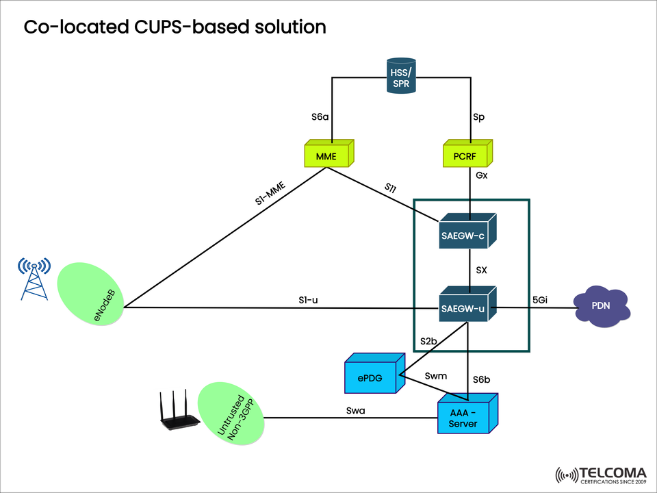
The image above shows a CUPS-based solution that keeps control and user plane components together at the same physical location, yet still takes advantage of the principles of CUPS. Let’s explore the architecture, its interfaces, and why it’s technically significant.
What is CUPS in LTE?
CUPS (Control and User Plane Separation) is an architectural advancement defined by 3GPP Release 14 for the EPC system. It facilitates the independent scaling, deployment, and development of both control and user plane functions.
Control Plane (C-plane): This manages signaling, mobility, session setups, and policy enforcement.
User Plane (U-plane): This is in charge of forwarding the actual data traffic from users (IP packets).
By separating these functions, operators can enhance:
Performance: Place U-plane nodes nearer to users to reduce latency.
Scalability: Scale the C-plane and U-plane independently based on current needs.
Flexibility: Support edge computing and make the transition to 5G smoother.
Co-Located CUPS-Based Solution Architecture
The co-located solution keeps both components of the Serving and PDN Gateway (SAEGW)—control and user planes—together at the same site, but they're logically segregated. This approach simplifies operations while getting networks ready for distributed setups down the line.
Key Components in the Diagram
eNodeB (Evolved NodeB):
Connects user devices to the EPC.
Interfaces:
S1-MME: Signals with MME.
S1-U: Sends user data to SAEGW-U.
MME (Mobility Management Entity):
Core control plane unit for mobility, session management, and authentication.
Connects to HSS/SPR and SAEGW-C.
Interface: S11 (with SAEGW-C).
HSS/SPR (Home Subscriber Server / Subscription Profile Repository):
Stores subscriber information, profiles, and authentication details.
Provides data over the S6a interface.
PCRF (Policy and Charging Rules Function):
Oversees QoS and charging rules.
Links to SAEGW-C via the Gx interface.
SAEGW-C (Serving and PDN Gateway – Control Plane):
Manages session setups and policy enforcement.
Communicates with SAEGW-U using the Sx interface.
SAEGW-U (Serving and PDN Gateway – User Plane):
Forwards user data packets to the external Packet Data Network (PDN).
Provides the actual path for user traffic.
ePDG (Evolved Packet Data Gateway):
Supports untrusted non-3GPP access (like Wi-Fi).
Collaborates with the AAA server for user authentication.
AAA Server (Authentication, Authorization, and Accounting):
Ensures security for non-3GPP access.
Interfaces:
Swa/Swm: With ePDG.
S6b: With SAEGW-U.
PDN (Packet Data Network):
External IP networks like the Internet or private enterprise networks.
Connected via the SGi/5Gi interface from SAEGW-U.
Interfaces in Co-Located CUPS Solution
The setup relies on well-defined interfaces to make sure everything works smoothly together:
InterfaceConnectsFunctionS1-MMEeNodeB ↔ MME Control signalingS1-UeNodeB ↔ SAEGW-U User plane trafficS11MME ↔ SAEGW-C Session managementS6aMME ↔ HSS/SPR Authentication and mobility SpPCRF ↔ SPR Policy and subscriber data GxPCRF ↔ SAEGW-CQoS and charging control Sx SAEGW-C ↔ SAEGW-UCUPS coordinationS2bePDG ↔ SAEGW-UNon-3GPP access user traffic Swm/Swae PDG ↔ AAA Authentication/authorizationS6bAAA ↔ SAEGW-U Security for non-3GPP access SGi/5GiSAEGW-U ↔ PDN Internet/enterprise connectivity
Benefits of Co-Located CUPS-Based Solution
While control and user plane components are kept together, the logical separation provides notable advantages:
Simplified Evolution: Operators can transition to distributed CUPS setups without a hitch.
Scalability: The independent scaling of C-plane and U-plane can happen within the same site.
Low Latency: Co-location diminishes signaling delays and helps support high-throughput services.
Cost-Efficient: Easier to deploy than fully distributed CUPS while paving the way for 5G advancements.
Support for Non-3GPP Access: Integration of ePDG and AAA guarantees seamless Wi-Fi and LTE connectivity.
Network Flexibility: Ready for edge computing integration and 5G core transition.
Use Cases of Co-Located CUPS Solution
Mobile Broadband Expansion:
Delivering high-speed LTE broadband in urban and suburban areas.
Enterprise Solutions:
Supporting private networks and secure access to PDNs for enterprises.
Seamless Wi-Fi Integration:
Enabling secure connections for users over untrusted Wi-Fi through ePDG and AAA.
5G Migration Path:
Prepares the EPC architecture for a service-based architecture (SBA) in 5G.
Enhanced Policy Control:
PCRF ensures dynamic QoS management for services like video streaming and VoLTE.
Co-Located vs. Distributed CUPS
Feature Co-Located CUPS Distributed CUPSD eployment Control and User planes on the same site C-plane and U-plane at different locations Latency Lower, thanks to proximity Optimized further with U-plane at the edge Scalability Moderate, limited by site High, with independent scaling Complexity Easier to manage Requires orchestration and complex design5G Readiness Transitional step Fully aligned with 5G core principles
Challenges in Co-Located CUPS Deployment
Limited Edge Optimization: Unlike distributed CUPS, the user plane can’t always be positioned closer to where users are.
Site Dependency: Scaling may need more physical resources at the same site.
Transition Complexity: Moving to a fully distributed CUPS setup takes careful planning.
Even with these challenges, co-located CUPS strikes a good balance between operational ease and future readiness.
Conclusion
The Co-located CUPS-based solution marks a significant evolutionary move in LTE network architecture. By logically separating control and user planes while keeping them physically together, operators gain flexibility, scalability, and a sound footing for future 5G development.
For telecom professionals, grasping this architecture is crucial for network planning, optimization, and transitioning to 5G. For tech enthusiasts, it shows how modern networks tackle massive data demands while ensuring efficient, secure connectivity.
As operators move towards distributed CUPS and eventually to 5G Core, the co-located solution stands as a practical, cost-effective, and technically solid foundation for today’s LTE networks.