
CU/DU Deployment in 5G: How Flexible Architectures Meet Diverse Service Needs

CU/DU Deployment in 5G: Adapting to Diverse Service Needs with Network Slicing
In the fast-changing world of 5G, having flexibility, scalability, and low latency is crucial. Unlike older generations where everything was tightly integrated, 5G breaks things apart—we've got the Central Unit (CU), Distributed Unit (DU), and Radio Unit (RU) all working somewhat independently.
This separation gives operators the chance to deploy these units where they’ll work best—whether that’s at the Edge, in Regional, or Central Data Centers—depending on what services they need to provide.
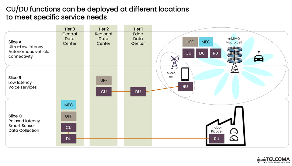
The image above shows how CU/DU deployment strategies adjust to different network slices for things like autonomous vehicles, voice services, and industrial IoT. Let's dig into how this flexibility leads to effective, tailored 5G performance for various applications.
Understanding CU/DU/RU in 5G RAN Architecture
The 5G Radio Access Network (RAN) is broken down into three main parts:
RU (Radio Unit): Takes care of radio frequency (RF) functions like sending and receiving signals at cell sites (macro, micro, or indoor small cells).
DU (Distributed Unit): Handles real-time baseband processing like scheduling, error correction, and resource management.
CU (Central Unit): Manages non-real-time, higher-layer protocols such as PDCP (Packet Data Convergence Protocol) and RRC (Radio Resource Control).
By decoupling these functions, 5G allows for dynamic placement of CU and DU units, optimizing for latency, cost, and overall performance.
Why Flexible CU/DU Deployment Matters
Different applications have unique Quality of Service (QoS) needs. For instance:
Autonomous driving needs ultra-low latency and high reliability.
Voice services require stable, moderate latency and dependability.
IoT sensors focus on energy efficiency and scalability, meaning they can handle relaxed latency.
The 5G network takes care of this with Network Slicing, where each “slice” is a tailored, end-to-end network designed to meet the specific performance demands of an application.
Flexible CU/DU placement makes sure computing resources are close to where they’re needed, improving efficiency and minimizing latency.
The Three-Tier Deployment Framework
The diagram showcases three tiers of 5G data centers where CU/DU components can be located:
Tier 1: Edge Data Center -- Closest to users/devices; provides ultra-low latency.
Tier 2: Regional Data Center -- Balances latency and resource usage.
Tier 3: Central Data Center – Centralized, cost-effective, better for tasks where latency isn’t a major concern.
Slice A – Ultra-Low Latency for Autonomous Vehicles
Use Case: Autonomous vehicles and mission-critical applications
Service Requirements:
Latency: <1 ms
Reliability: Extremely high
Bandwidth: High
Computing proximity: Edge
Deployment Strategy:
RU, DU, and CU are all close to the Edge Data Center (Tier 1).
User Plane Function (UPF) and Multi-access Edge Computing (MEC) components are co-located with the DU for speedy data processing.
The mMIMO (Massive MIMO) macro cell offers wide coverage and high throughput.
Benefits:
Instant communication for vehicle-to-everything (V2X) systems.
Minimal backhaul latency.
Supports real-time decision making for things like collision avoidance or autonomous driving.
This edge-centric setup ensures data doesn’t have to travel back to a central core before decisions are made—vital for ultra-low latency reliability.
Slice B – Low Latency for Voice and Real-Time Communication
Use Case: Voice calls, video conferencing, and real-time communication apps
Service Requirements:
Latency: Moderate (5–10 ms)
Reliability: High
Bandwidth: Medium
Cost: Optimized deployment
Deployment Strategy:
RU is at the access site (micro cell).
DU is at a Regional Data Center (Tier 2).
CU and UPF functions might be centralized but positioned nearby to maintain real-time performance.
This structure balances performance and cost, allowing for large-scale deployments while keeping good latency for voice and interactive services.
Benefits:
Better network utilization.
Less backhaul congestion.
High service continuity with redundancy at the regional level.
Slice C – Relaxed Latency for IoT and Smart Sensors
Use Case: Smart factories, environmental sensors, and metering systems
Service Requirements:
Latency: Relaxed (can handle delays)
Bandwidth: Low
Power consumption: Low
Reliability: Moderate
Deployment Strategy:
RU (e.g., indoor picocell) operates in industrial settings.
DU and CU could be at Central Data Centers (Tier 3).
UPF and MEC functions can be shared across multiple applications to keep costs down.
Benefits:
Cuts down operational expenses (OPEX) by managing resources centrally.
Easier network configuration.
Efficient for connecting numerous IoT devices.
In this slice, latency isn’t critical, so processing can take place centrally, which boosts efficiency and lowers the costs of edge infrastructure.
Multi-Access Edge Computing (MEC) Integration
MEC is essential for improving application performance by processing data nearer to where it’s generated. In the diagram:
MEC nodes appear alongside DU or CU components at Edge Data Centers.
They manage application-specific tasks, analytics, and AI-driven enhancements.
Key MEC Advantages:
Real-time analytics for IoT and AI applications.
Improved QoS for workloads sensitive to latency.
Less load on backhaul by processing data locally.
Integrating MEC with CU/DU deployments lets operators achieve low-latency service delivery while also boosting network efficiency.
Benefits of Flexible CU/DU Deployment in 5G
a. Optimized Latency
Positioning DU and CU where they belong minimizes delay for applications that need quick responses.
b. Cost Efficiency
Centralizing non-critical tasks helps lower operational costs.
c. Scalability
Dynamic deployment lets operators scale services effortlessly across various regions.
d. Energy Efficiency
Less traffic on backhaul and edge offloading improve energy consumption across the network.
e. Service Customization
Different network slices can operate together on the same infrastructure, catering to various sectors like automotive, healthcare, and manufacturing.
Practical Example: Industrial Smart Factory
In a smart manufacturing facility, indoor picocells (RU) connect to centralized DU and CU units housed at a data center. This setup makes it possible for:
Ongoing data collection from sensors.
Predictive maintenance through AI analytics (processed in MEC).
Steady connectivity across robotic arms, conveyor systems, and IoT platforms.
Thanks to the relaxed latency tolerance, centralizing resources remains cost-effective without sacrificing reliability.
Key Takeaways
Aspect Edge (Tier 1)Regional (Tier 2)Central (Tier 3)Latency Ultra-low Moderate Relaxed Use Case Autonomous driving Voice IoT sensors Deployment Focus Performance Balance Cost-efficiency CU/DU Location Co-located Split Centralized MEC Presence High Moderate Optional
This flexible setup makes sure you get the right service, at the right place, with the right resources.
Conclusion
The flexible deployment of CU/DU functions is central to 5G’s ability to deliver ultra-reliable, low-latency, and scalable connectivity. By smartly distributing network functions across Edge, Regional, and Central Data Centers, operators can customize performance for different network slices—whether it’s for autonomous driving, voice communication, or IoT data collection.
This adaptability not only enhances user experiences but also cuts down operational expenses, optimizes network efficiency, and sets the stage for intelligent, service-aware 5G networks in the future.