
Demystifying the Sounding Reference Signal (SRS) in 5G NR: Structure, Purpose, and Configuration Explained

Understanding Sounding Reference Signal (SRS) in 5G NR
In 5G New Radio (NR), uplink transmission is crucial for providing the network with channel state information (CSI). A key player in this is the Sounding Reference Signal (SRS).
The SRS lets the gNB (5G base station) evaluate uplink channel quality, assess frequency selectivity, and make informed choices about beamforming, scheduling, and link adaptation.
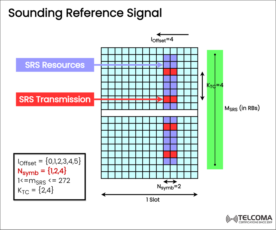
The image uploaded from Telcoma vividly illustrates how SRS resources and transmissions fit into a time-frequency grid, which helps clarify this important aspect of uplink channel sounding.
What is the Sounding Reference Signal (SRS)?
The Sounding Reference Signal (SRS) is a specific uplink reference signal sent by the User Equipment (UE) to the gNB. Its main job is uplink channel estimation, enabling the base station to understand how the radio channel behaves across various frequencies and times.
Put simply:
SRS allows the base station to “listen” to the conditions of uplink channels before it assigns resources for data transmission.
This results in:
Efficient uplink scheduling
Frequency-selective resource allocation
Enhanced MIMO beamforming
Dynamic spectrum utilization
Why SRS is Important in 5G Networks
The 5G system operates over different frequency bands (sub-6 GHz and mmWave), each with unique propagation characteristics. Getting accurate channel info is vital for:
Adaptive Modulation and Coding (AMC)
Carrier aggregation decisions
Uplink power control
Beam management in massive MIMO
Unlike the DMRS (Demodulation Reference Signal), used for decoding actual data, the SRS is a probing signal that the network utilizes even before any uplink data is sent, helping the gNB get ready with transmission parameters.
Analyzing the Image: 5G NR SRS Resource Structure
The displayed image outlines the time-frequency structure of SRS in a single slot. Let’s go over its main elements.
Time-Frequency Grid
The grid depicts one slot in the NR frame structure, made up of 14 OFDM symbols in time and several Resource Blocks (RBs) in frequency.
The blue cells show available SRS resources for configuration.
The red cells mark SRS transmission instances.
Each vertical column signifies subcarriers, and each horizontal line corresponds to an OFDM symbol.
Key Parameters Defined
The image highlights several essential SRS parameters that detail how and where SRS is mapped:
Parameter Symbol Description Offset𝑙offset Index that determines the start of SRS in time. Number of Symbols Nsymb Specifies the OFDM symbols used for SRS transmission (1, 2, or 4).SRS Bandwidth MSRS Bandwidth allocated to SRS in Resource Blocks (RBs).Frequency Comb KTC Sets frequency spacing between SRS subcarriers (2 or 4).SRS Resource Index mSRS Identifies a specific SRS resource within the configuration (1 ≤ mSRS ≤ 272).
Each of these parameters influences how the SRS is transmitted and how much channel data the gNB can gather.
- SRS Transmission Process
The image illustrates the SRS Transmission (marked by a red arrow) highlighting a group of red-highlighted resource elements that correspond to the active SRS symbols sent by the UE.
This transmission takes place over a set of time slots as defined by the SRS configuration that the gNB provides through RRC signaling.
The SRS Resources (shown with a blue arrow) indicate resources that might be used for SRS, depending on scheduling requirements.
SRS Configuration Parameters Explained
The structure and placement of SRS depend on multiple configuration parameters set by 3GPP (TS 38.211, Section 6.4.1.4).
- Ioffset
Indicates the starting position of the SRS in the time domain within a slot.
Possible values: {0, 1, 2, 3, 4, 5}
It ensures SRS doesn’t conflict with other uplink signals like PUSCH or PUCCH.
Types of SRS in 5G NR
5G NR accommodates multiple SRS types, depending on their purpose:
Periodic SRS * Sent at regular intervals. * Used for continuous uplink channel tracking.
Aperiodic SRS * Triggered on-demand by the gNB via DCI messages. * Handy for immediate channel measurement.
Semi-Persistent SRS (SP-SRS) * Combines features of periodic and aperiodic SRS. * Offers flexibility for time-sensitive tasks.
SRS Resource Allocation and Multiplexing
- Frequency Domain Multiplexing
Multiple UEs can send SRS at the same time on different frequency bands using distinct MSRS or KTC values.
- Time Domain Multiplexing
UEs can also be timed separately using Ioffset or Nsymb setups to prevent overlap.
- Code Domain Multiplexing
Orthogonal cover codes are implemented when SRS resources intersect, allowing several UEs to share the same frequency and time domain resources.
These multiplexing methods ensure SRS remains scalable and efficient in massive MIMO and dense network situations.
Practical Use Cases of SRS
SRS is key to enabling advanced 5G features like:
Beam Management: Assists gNB in finding the best beam directions for uplink transmission.
Uplink Scheduling: gNB selects frequency bands with the best channel conditions for each UE.
Carrier Aggregation: Facilitates cross-carrier channel estimation to enhance overall throughput.
Massive MIMO Precoding: Precise uplink CSI aids in calculating optimal precoding matrices.
Interference Management: Identifies and reduces inter-cell interference using SRS-based measurements.
Example: How SRS Works in a 5G Cell
Configuration: The gNB sets SRS parameters (offset, bandwidth, symbol count) for the UE.
Transmission: The UE sends SRS during designated slots using the specified resources.
Measurement: The gNB measures the received power, delay, and phase shifts to gauge the channel response.
Optimization: Based on the SRS input, the gNB adjusts scheduling, MCS levels, and beam directions.
This cycle keeps repeating, ensuring the uplink stays optimized in real time.
Comparison: SRS vs DMRS
Purpose Channel sounding and uplink estimation Channel estimation for demodulation
Transmission Timing Independent (can occur without data)With PUSCH/PUCCH data
Direction Uplink only Both uplink and downlink
Coverage Wide frequency band Narrow, localized to data transmission
Configuration Semi-static or dynamic Per transmission
Conclusion
The Sounding Reference Signal (SRS) is a vital tool in 5G NR uplink design, enabling accurate channel estimation and adaptive resource allocation.
As shown in the accompanying image, SRS operates across designated time-frequency resources governed by parameters like Ioffset, Nsymb, MSRS, and KTC, allowing flexible and scalable use for various network scenarios.
To sum up, SRS helps 5G networks “listen” to the uplink channel, paving the way for smarter scheduling, effective beamforming, and a better user experience.