
EN-DC Overall Architecture Explained: LTE and 5G Dual Connectivity

EN-DC Overall Architecture in LTE and 5G
As mobile networks continue to rapidly advance, moving from LTE to 5G has introduced various deployment models aimed at ensuring a smooth transition and an improved user experience. A key technology in this evolution is EN-DC (E-UTRAN New Radio – Dual Connectivity), which enables user equipment (UE) to connect to both LTE and 5G NR nodes at the same time.
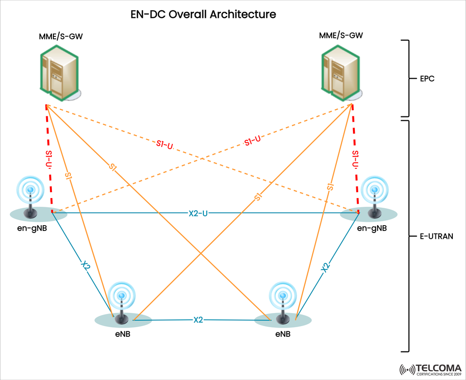
The diagram provided shows the EN-DC Overall Architecture, detailing how the EPC (Evolved Packet Core) interacts with LTE eNBs and 5G gNBs, as well as how different interfaces like S1, S1-U, and X2 manage signaling and data flows. Let’s delve into this architecture.
What is EN-DC?
EN-DC (E-UTRAN New Radio – Dual Connectivity) is a feature from 3GPP Release 15 that supports dual connectivity between:
Master Node (MN): Usually an LTE eNB that anchors the control plane.
Secondary Node (SN): A 5G gNB (or en-gNB) that offers extra user plane resources.
This setup guarantees:
High data throughput by combining LTE and NR carriers.
Compatibility with existing LTE EPC.
A smooth user experience during mobile transitions.
Key Components in EN-DC Architecture
- EPC (Evolved Packet Core)
The EPC remains the core network in EN-DC. It features:
MME (Mobility Management Entity): Responsible for signaling, authentication, and session management.
S-GW (Serving Gateway): Handles user plane traffic between RAN and EPC.
In the diagram:
The EPC connects to eNBs and en-gNBs using S1 interfaces (for signaling) and S1-U interfaces (for user plane).
- E-UTRAN (Access Network)
The E-UTRAN within EN-DC includes LTE eNBs and en-gNBs (5G NR nodes that support EPC).
eNB (LTE Node):
Functions as the Master Node (MN) in most EN-DC setups.
Manages control-plane signaling with the EPC.
Provides user-plane connectivity via S1-U.
en-gNB (Next-Gen gNB with EPC support):
Serves as the Secondary Node (SN) in EN-DC.
Offers additional user-plane capacity using 5G NR spectrum.
Connected to EPC through S1-U and to eNBs via the X2 interface.
In the illustration:
eNBs and en-gNBs link up through X2 connections.
The EPC connects directly to both eNB and en-gNB, providing flexibility.
EN-DC Interfaces Explained
The diagram outlines several important interfaces in the EN-DC architecture:
S1 (Signaling Interface): Connects EPC (MME) with eNB/en-gNB for control plane signaling.
S1-U (User Plane Interface): Links EPC (S-GW) with eNB/en-gNB for user plane data flow.
X2 (LTE X2 Interface): Connects eNBs to each other and links eNBs to en-gNBs for coordination purposes.
X2-U (User Plane on X2): Specifically used for transferring user plane data between eNB and en-gNB.
These interfaces play a crucial role in effectively distributing signaling and data across LTE and 5G components.
How EN-DC Works (Step by Step)
UE connects to LTE eNB (Master Node):
Initial signaling and control procedures kick off through LTE.
MME anchors the control plane via the eNB.
Adding the Secondary Node (en-gNB):
Depending on UE capability and network conditions, the eNB sets up a secondary connection with the en-gNB using X2 signaling.
This allows for dual connectivity (LTE + NR).
Splitting User Plane:
The EPC directs user plane traffic to both eNB and en-gNB via S1-U.
Alternatively, the eNB can route a portion of that traffic to the en-gNB through X2-U.
Data aggregation at UE:
The UE gets data from both LTE and 5G NR at the same time.
Packets are combined for better throughput and reliability.
Advantages of EN-DC
EN-DC comes with several advantages during the LTE-to-5G transition:
Higher Throughput: Combines spectrum resources from LTE and NR.
Seamless Evolution: Utilizes the existing LTE EPC without requiring immediate 5G Core (5GC) installation.
Improved Reliability: LTE maintains stable connectivity if NR coverage is limited.
Efficient Spectrum Use: Takes advantage of both licensed LTE spectrum and new 5G bands.
Mobility Support: Facilitates smooth handovers between LTE and 5G.
EN-DC Architecture Summary (Table)
Component Role in EN-DC Key Interfaces EPC (MME + S-GW)Manages control and user plane trafficS1, S1-UeNB (Master Node)Anchors control plane, manages UE connectionS1, S1-U, X2en-gNB (Secondary Node)Provides additional NR user plane resourcesS1-U, X2-UUE (User Equipment)Connects simultaneously to LTE and NR-Interfaces Connects EPC and RAN nodesS1, S1-U, X2, X2-U
EN-DC vs 5G Standalone (SA)
It’s essential to differentiate EN-DC from 5G Standalone (SA):
EN-DC (NSA – Non-Standalone):
Relies on EPC (LTE Core).
LTE anchors the control plane, while 5G NR boosts data throughput.
Faster to deploy and maintains backward compatibility.
5G Standalone (SA):
Utilizes the new 5G Core (5GC).
5G NR manages both control and user planes.
Enables advanced features like network slicing and ultra-low latency.
In short, EN-DC is a bridge technology that helps operators roll out 5G quickly while still using LTE infrastructure.
Real-World Deployment Scenarios
Urban Areas: EN-DC enhances capacity by merging LTE macro coverage with 5G small cells.
Suburban/Rural Areas: LTE offers broad coverage, while NR contributes extra speed when available.
Enterprise Networks: Dual connectivity provides both reliable LTE and high-speed NR for critical business services.
Conclusion
The EN-DC Overall Architecture allows operators to provide 5G-like experiences while taking advantage of their existing LTE infrastructure. By merging LTE eNBs (Master Nodes) with 5G en-gNBs (Secondary Nodes) through EPC and interfaces like S1, S1-U, and X2, networks achieve better throughput, enhanced coverage, and easier mobility.
For those in the telecom field, having a solid grasp of EN-DC is vital since it marks a practical step in the journey from 4G to 5G. It enables operators to juggle costs, performance, and deployment schedules while giving users a preview of what 5G has to offer before fully adopting standalone solutions.