
EPS-5G Core Network Architecture: Interfaces, Components, and Interworking Explained

Introduction: The Importance of EPS-5G Interworking
5G networks don't just operate on their own; they work alongside existing LTE/EPS systems to ensure a smooth transition and uninterrupted connectivity for billions globally. This is crucial for several reasons:
LTE offers the wide coverage and maturity that 5G is still developing.
5G brings incredibly fast speeds, low latency, and extensive connectivity to the table.
The combination of EPS and 5G guarantees service continuity while operators gradually roll out 5G.
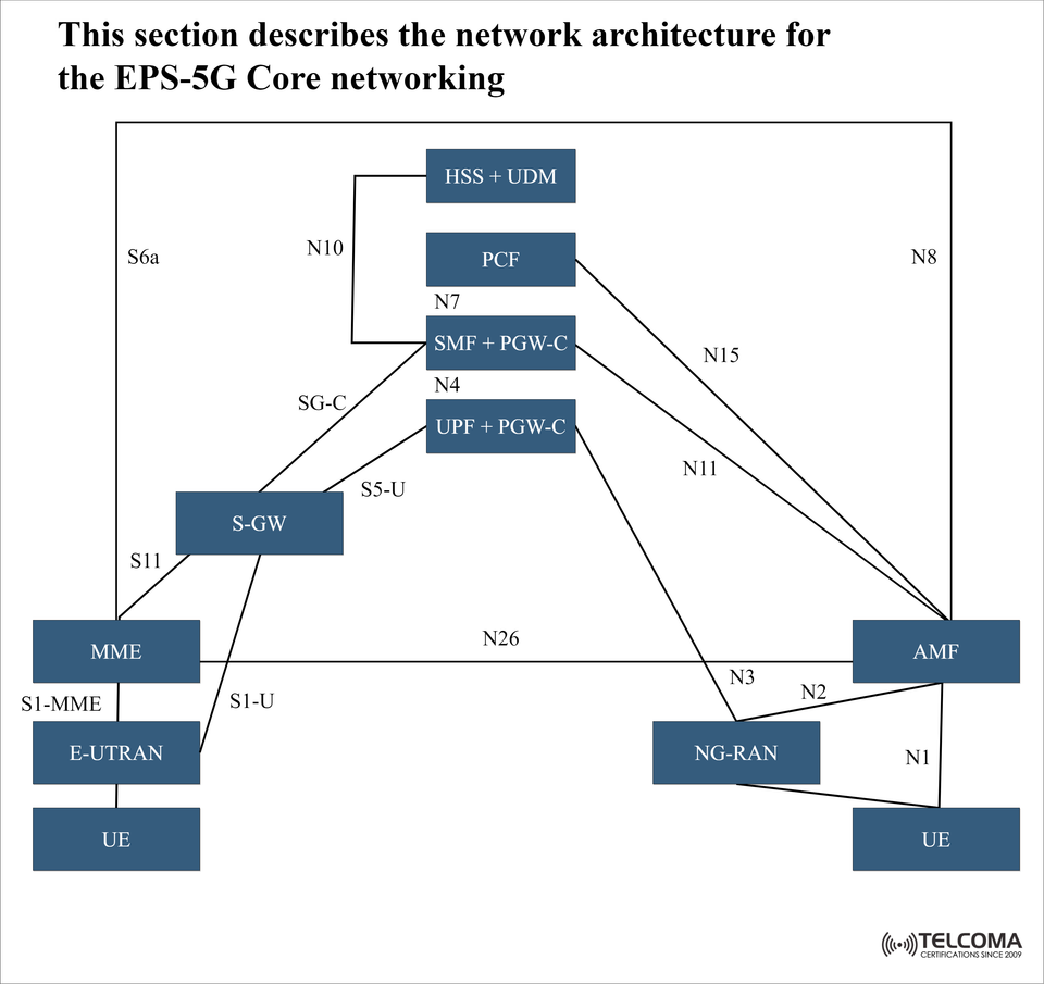
The diagram above shows the EPS-5G core architecture, highlighting how LTE’s EPC (Evolved Packet Core) interacts with the 5G Core (5GC) through standardized 3GPP interfaces.
Key Network Components in EPS-5G Architecture
- User Equipment (UE)
This includes mobile devices like smartphones and IoT modules.
They connect through either E-UTRAN (LTE radio access) or NG-RAN (5G radio access).
With dual connectivity, the same UE can access both LTE and 5G cores without a hitch.
- E-UTRAN (Evolved UMTS Terrestrial Radio Access Network)
This is the LTE radio network that links the UE to the EPC.
It uses S1-MME (control plane) and S1-U (user plane) interfaces towards the EPC.
It remains essential for fallback coverage when 5G NR isn't available.
- MME (Mobility Management Entity)
This handles signaling, mobility, and session management in LTE.
It connects with the HSS, SGW, and AMF for 5G interworking.
Think of it as the brain of the LTE control plane.
- Serving Gateway (S-GW)
The user plane node in the EPC routes and forwards user data packets.
It connects to the PDN Gateway (PGW) and also supports links to UPF in 5GC now.
- HSS (Home Subscriber Server) + UDM (Unified Data Management)
The HSS holds subscriber data for LTE.
The UDM does the same for 5G.
Together, they provide a common authentication and subscriber management layer for both LTE and 5G.
- AMF (Access and Mobility Management Function)
This is the 5G counterpart of the MME.
It manages UE registration, mobility, and access authentication.
It connects with the MME via N26 for interworking.
- SMF (Session Management Function) + PGW-C
The SMF in 5GC handles session setup and management.
The PGW-C (Control plane of the Packet Gateway) ensures session continuity with LTE EPC.
This combined node allows both LTE and 5G to share control over data sessions.
- UPF (User Plane Function) + PGW-U
The UPF acts as the anchor for user plane traffic in 5G.
PGW-U performs similar functions in LTE.
Together, they ensure data continuity across networks, even during inter-RAT handovers.
- PCF (Policy Control Function)
This is the successor to PCRF (Policy and Charging Rules Function).
It provides unified policy control for both LTE and 5G sessions.
It ensures consistent QoS enforcement across networks that are interworking.
Important Interfaces in EPS-5G Core
The diagram highlights some standardized interfaces that are key for EPS-5G integration:
S1-MME / S1-U – UE ↔ E-UTRAN ↔ MME/SGW (LTE access).
N1, N2, N3 – UE ↔ NG-RAN ↔ AMF/UPF (5G access).
N26 – Connection between MME and AMF for smooth mobility and session continuity.
N10 – Link between HSS and UDM, coordinating subscriber management.
N7, N15 – Between SMF/PGW-C and PCF for policy control.
N4 – Between SMF and UPF, which manages user plane traffic.
S6a – MME ↔ HSS (managing LTE subscriptions).
S11 / SG-C – MME ↔ SGW (control plane for LTE).
These interfaces enable dual connectivity, mobility management, and session handovers between EPS and 5G.
How EPS-5G Core Networking Functions in Practice
As a UE moves between LTE and 5G, the network ensures service continuity through interworking:
Initial Connection: * If LTE coverage is stronger, the UE connects via MME → SGW → PGW. * If 5G coverage is available, it connects through AMF → SMF → UPF.
Mobility Event (e.g., LTE → 5G handover): * The MME communicates with the AMF using the N26 interface. * Session data is shared to maintain continuity without call drops.
Policy Enforcement: * The PCF enforces QoS rules for both LTE and 5G sessions. * This guarantees a consistent user experience across networks.
Data Flow: * User data passes through SGW/PGW (for LTE) or UPF (for 5G). * Control signaling is managed by MME (for LTE) or AMF/SMF (for 5G).
This setup ensures seamless mobility and inter-RAT continuity.
Benefits of EPS-5G Core Integration
Smooth Migration: Operators can gradually roll out 5G without disrupting existing LTE services.
Dual Connectivity: Users can access both LTE and 5G simultaneously for better throughput.
Efficient Spectrum Utilization: LTE and 5G collaborate to maximize spectrum efficiency.
Service Continuity: Handoffs between LTE and 5G are smooth.
Unified Policy Management: PCF maintains QoS across both networks.
EPS-5G Core vs. Standalone 5G Core
FeatureEPS-5G Core (Non-Standalone)Standalone 5G Core Control Plane Shared between MME & AMF Pure AMF/SMF architecture User Plane SGW/PGW + UPF coexist Only UPF Policy Control PCF + legacy PCRFPCF only Deployment Gradual, LTE-dependent Independent 5GBest Use Case Migration phase Full 5G rollout
This illustrates why EPS-5G interworking is a necessary transition phase for global operators.
Conclusion
The EPS-5G core network architecture effectively bridges the gap between the established LTE EPC and the new 5G core, allowing users to enjoy uninterrupted service as we transition to 5G.
By integrating MME, SGW, HSS, and PGW from LTE with AMF, SMF, UPF, and PCF from 5G, operators can achieve:
Seamless mobility between LTE and 5G.
Consistent policy and QoS management.
Future-ready pathways to standalone 5G networks.
For telecom professionals, grasping EPS-5G architecture is key to planning deployments, optimizing handovers, and delivering the reliable connectivity that 5G applications require.
Real-World Deployment Scenarios of EPS-5G Core
Operators around the globe are adopting Non-Standalone (NSA) 5G, which relies on EPS-5G interworking, before making the leap to Standalone (SA) 5G.
Example Use Cases:
Urban Areas: 5G NR is rolled out in hotspots for high speeds, while LTE covers the surrounding areas. UEs can transition smoothly between EPS and 5GC.
IoT Deployments: Low-power IoT devices might stick with LTE for reliability, while high-bandwidth applications (like AR/VR) would leverage 5G with UPF.
Enterprise Networks: Businesses utilize hybrid LTE/5G networks, ensuring older LTE devices function smoothly while new apps take advantage of 5G’s low latency.
This hybrid EPS-5G model is not just a temporary phase; it’s also a strategic approach for maximizing spectrum efficiency and optimizing costs.