
FR2 Maximum Transmission Bandwidth Configuration in 5G NR | 60 kHz and 150 kHz SCS Explained

5G New Radio (NR) splits its spectrum into two key frequency ranges: FR1 (below 6 GHz) and FR2 (mmWave, spanning 24.25–52.6 GHz). FR1 is all about coverage and reliability, while FR2 brings super high bandwidth and ultra-fast data rates—which are crucial for the next-gen applications we’re looking at, such as:
High-capacity mobile broadband (eMBB)
Fixed wireless access (FWA)
Immersive augmented reality/virtual reality (AR/VR) experiences
Autonomous systems that need less than a millisecond of latency.
To tap into these powerful features, 3GPP outlines the maximum configurations for transmission bandwidths. This includes details on how many Resource Blocks (RBs) fit within a specific Subcarrier Spacing (SCS) and channel bandwidth.
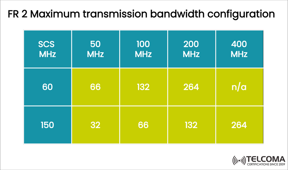
The chart we've uploaded gives you a clear overview of these configurations for FR2.
Understanding the FR2 Bandwidth Configuration Table
SCS (kHz) 50 MHz 100 MHz 200 MHz 400 MHz
60 kHz 66 132 264 N/A
150 kHz 32 66 132 264
Interpretation
This table shows how many Resource Blocks (RBs) can be assigned for each channel bandwidth at a specific Subcarrier Spacing (SCS). Each RB has 12 subcarriers, and the spacing for each subcarrier is based on the SCS (Δf).
Higher SCS → Shorter OFDM symbol duration → Lower latency
Lower SCS → More RBs in a fixed bandwidth → Better spectral efficiency
FR2 Subcarrier Spacing Options
a) 60 kHz SCS
This is mostly used for the lower FR2 frequencies (24–40 GHz). The 60 kHz SCS strikes a nice balance between spectral efficiency and latency.
Key characteristics:
66 RBs in 50 MHz
132 RBs in 100 MHz
264 RBs in 200 MHz
No defined configuration for 400 MHz at 60 kHz (due to spectral and hardware limitations)
b) 150 kHz SCS
This was introduced for the higher FR2 frequencies (up to 52.6 GHz) and delivers very short slot durations, which is vital for ultra-low latency and quick scheduling.
Key characteristics:
32 RBs in 50 MHz
66 RBs in 100 MHz
132 RBs in 200 MHz
264 RBs in 400 MHz
How Subcarrier Spacing Influences Bandwidth Efficiency
In OFDM-based 5G NR systems, the SCS determines how many subcarriers can fit within a given bandwidth.
With 60 kHz, more subcarriers fit per MHz → more RBs → higher potential throughput.
With 150 kHz, fewer subcarriers fit → fewer RBs → slightly lower spectral efficiency but better latency and improved Doppler resilience.
So, it’s really about finding that balance between capacity and latency:
SCS (kHz) Symbol Duration (µs) Slot Duration (ms) Use Case
60 16.67 0.25 eMBB, FWA
150 6.67 0.1 URLLC, AR/VR, Industrial IoT
Why FR2 Needs Wide Bandwidths
FR2 breaks the limits of FR1, which tops out at 100 MHz, allowing for channel widths up to 400 MHz. This huge bandwidth means:
Gigabit+ data rates per user
Support for high user densities
Low latency operations
On the flip side, FR2’s higher frequencies encounter significant propagation losses and have shorter coverage, so it’s often deployed in small-cell architectures.
Example: Estimating Throughput in FR2
Let’s work out the theoretical throughput for a 400 MHz channel using 150 kHz SCS (which includes 264 RBs):
Each RB = 12 subcarriers × 150 kHz = 1.8 MHz
Total usable bandwidth = 264 × 1.8 MHz = 475.2 MHz
Using 256-QAM modulation and 4×4 MIMO:
Throughput = 475.2 MHz × 8 bits/symbol × 4 layers × 0.93 ≈ 14.1 Gbps
This illustrates FR2’s ability to deliver multi-Gbps data rates, even for individual users in ideal conditions.
The Connection Between RBs and Spectral Efficiency
How many Resource Blocks (RBs) you have affects how you allocate frequencies. Fewer RBs (with a higher SCS) mean:
Less flexibility in scheduling
More signal robustness against Doppler spread
Better performance in dense or highly mobile environments
On the other hand, denser RB configurations (like 60 kHz SCS) allow for finer control over dynamic scheduling, but they require more computational power and precise synchronization.
Deployment Scenarios for 60 kHz and 150 kHz
SCS (kHz) Deployment Range (GHz) Typical Application Deployment Type
60 24.25–40 eMBB, FWA Outdoor small cells
150 40–52.6 URLLC, AR/VR, V2X Indoor hotspots, Industrial IoT
Design and Hardware Considerations
Implementing 150 kHz SCS at FR2 does require:
High-speed DACs/ADCs
Advanced phase noise suppression
Beamforming antennas that can adapt
Plus, the RF front-end design has to ensure efficiency and linearity across those wide bandwidths (up to 400 MHz). That’s why FR2 radios typically include massive MIMO arrays and beam tracking algorithms.
Challenges in Utilizing FR2 Bandwidth
While FR2 can support wide bandwidths, there are practical challenges:
Limited range (~100–300 meters)
Higher path loss (20–30 dB more than FR1)
Obstacles (walls, trees, rain) can block signals
Costly hardware and installation
To counteract these issues, operators use:
Dynamic beamforming
Carrier aggregation (FR1 + FR2)
Repeaters and reflectors
Comparing FR1 and FR2 Bandwidth Configurations
Parameter FR1 FR2
Frequency Range <6 GHz 24.25–52.6 GHz
Max Bandwidth 100 MHz 400 MHz
SCS Options 15, 30, 60 kHz 60, 150 kHz
Max RBs 270 264
Coverage Wide Limited
Use Case Coverage & reliability Speed & capacity
This comparison shows that FR1 serves as the coverage anchor, while FR2 functions as the capacity booster—together, they create true 5G performance.
Real-World Applications for FR2 Bandwidths
Fixed Wireless Access (FWA): Providing gigabit internet to homes
Stadiums and Concerts: Massive capacity for thousands of attendees
Smart Factories: Low-latency control for automation
Autonomous Vehicles: Fast data exchange for V2X communication
AR/VR in 5G: High bandwidth for real-time rendering
Conclusion
The FR2 maximum transmission bandwidth configuration is integral to realizing 5G NR’s promise for multi-gigabit performance. By using subcarrier spacings of 60 kHz and 150 kHz, 5G networks can effectively balance capacity, latency, and coverage based on what’s required for deployment.
Key takeaways include:
60 kHz SCS gives high spectral efficiency for moderate mmWave frequencies.
150 kHz SCS supports ultra-low latency and extreme throughput in high-frequency ranges.
400 MHz channels in FR2 pave the way for multi-Gbps user speeds for advanced 5G use cases.
As networks move toward 6G, FR2 configurations will likely keep evolving, supporting bandwidths that exceed 400 MHz—setting the stage for immersive, data-rich wireless experiences.