
FR2 Maximum Transmission Bandwidth Configuration in 5G NR: Complete Technical Guide

FR2 Maximum Transmission Bandwidth Configuration in 5G NR
The 5G NR (New Radio) framework aims to provide high throughput, low latency, and massive connectivity. A key factor that impacts the system’s capacity and efficiency is the maximum transmission bandwidth configuration — which essentially dictates how much spectrum is available for data transmission.
FR1 (Frequency Range 1) covers frequencies below 6 GHz, while FR2 (Frequency Range 2) zeroes in on millimeter-wave (mmWave) frequencies, ranging from 24.25 GHz to 52.6 GHz.
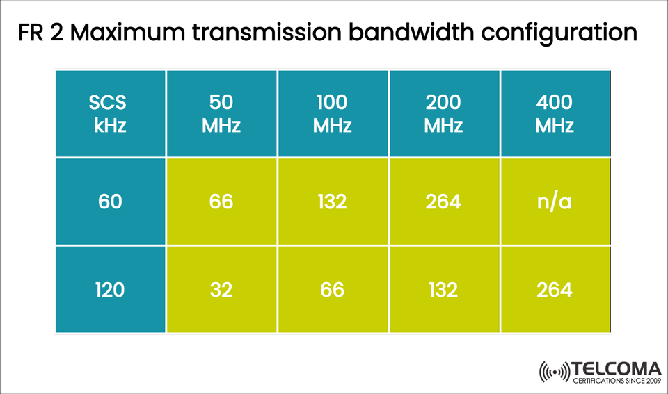
The image above gives a clear summary of the FR2 maximum bandwidth configurations based on different subcarrier spacings (SCS) and channel bandwidths.
Understanding FR2 in 5G NR
FR2 represents the high-frequency range in 5G that supports multi-gigabit data rates along with ultra-low latency. These bands offer:
Wider bandwidths (up to 400 MHz per carrier)
Huge capacity for high-demand data services
Shorter wavelengths, leading to highly directional beamforming
But there are downsides to these higher frequencies, like:
Increased path loss
Shorter coverage ranges
Greater vulnerability to blockages
To get around these challenges, FR2 uses advanced techniques like beamforming, massive MIMO, and dense small-cell networks.
Overview of FR2 Bandwidth Configuration
In 5G NR, the maximum bandwidth for each carrier is influenced by:
The subcarrier spacing (SCS)
The channel bandwidth (the spectrum assigned)
The frequency range (FR1 or FR2)
Below, the adapted table defines the maximum transmission bandwidth configuration for FR2:
SCS (kHz) | 50 MHz | 100 MHz | 200 MHz | 400 MHz
60 | 66 | 132 | 264 | n/a
120 | 32 | 66 | 132 | 264
These numbers reflect the maximum number of resource blocks (RBs) that can be set for a particular bandwidth and subcarrier spacing.
What’s a Resource Block (RB)?
A resource block (RB) is the smallest allocation unit in the 5G NR time-frequency grid. It represents a block of subcarriers (in frequency) for one slot (in time). Each RB is made up of:
12 subcarriers, and
1 slot duration (usually 14 OFDM symbols)
The total number of RBs in a channel bandwidth determines the usable transmission bandwidth. Generally, a higher RB count translates to increased data throughput.
FR2 Subcarrier Spacing (SCS) Options
In FR2, the 5G NR system supports two main subcarrier spacing (SCS) values:
Subcarrier Spacing (SCS) | Numerology (μ) | Typical Use
60 kHz | μ = 2 | Lower mmWave bands (~24–40 GHz)
120 kHz | μ = 3 | Higher mmWave bands (~40–52.6 GHz)
These larger SCS values lead to shorter symbol durations, which help reduce latency — great for URLLC (Ultra-Reliable Low Latency Communication) and eMBB (Enhanced Mobile Broadband) scenarios.
Still, shorter symbol times make the system more sensitive to delays, which means these setups work best in smaller cells and line-of-sight conditions typical for FR2.
Breaking Down the FR2 Bandwidth Configuration Table
Let’s decode the table values step by step:
At 60 kHz SCS:
A 50 MHz channel supports 66 RBs.
Doubling to 100 MHz increases RBs to 132.
At 200 MHz, the RB count again doubles to 264.
Beyond 200 MHz, 60 kHz SCS isn't defined for 400 MHz channels due to system limits.
At 120 kHz SCS:
The RB count kicks off lower because of the bigger subcarrier spacing.
32 RBs → 66 RBs → 132 RBs → 264 RBs as channel bandwidth goes up.
120 kHz SCS supports 400 MHz channels, which makes it capable of the widest bandwidth in 5G NR.
In summary:
Higher SCS means fewer RBs per MHz, but it allows for shorter slots and reduced latency, making it perfect for FR2 (mmWave).
Key Observations
FR2 only works with 60 kHz and 120 kHz SCS — higher numerologies are vital to tackle high Doppler spread and maintain low latency.
Maximum channel bandwidths can hit up to 400 MHz per carrier in FR2.
The highest RB count (264) is at 120 kHz SCS and a 400 MHz bandwidth.
Efficiency is influenced by bandwidth usage, guard bands, and FFT size settings.
Comparing FR2 and FR1 Bandwidth Configurations
Feature | FR1 (Sub-6 GHz) | FR2 (mmWave)
Frequency Range | < 6 GHz | 24.25 – 52.6 GHz
SCS Options | 15 / 30 / 60 kHz | 60 / 120 kHz
Max Channel Bandwidth | 100 MHz | 400 MHz
Max RBs | 270 | 264
Typical Use | Coverage, mobility | Capacity, low latency
FR2 gives up coverage for increased capacity and speed, while FR1 finds a balance between the two. Network operators often combine FR1 + FR2 carriers using Carrier Aggregation (CA) to attain both coverage and performance.
How FR2 Bandwidth Impacts Throughput
Achievable throughput in 5G NR hinges on:
Available RBs (transmission bandwidth configuration)
Modulation scheme (from QPSK to 256-QAM)
MIMO layers (for spatial multiplexing)
Code rate and efficiency
For instance:
A 120 kHz SCS paired with a 400 MHz bandwidth and 264 RBs could theoretically achieve multi-Gbps throughput, depending on MIMO and coding techniques.
This setup is usually found in mmWave bands, like n257 (26 GHz) and n261 (28 GHz).
Design Factors for FR2 Deployments
When planning FR2 bandwidth use, engineers need to take into account several things:
Propagation Loss: High frequencies have higher path loss, requiring smaller cells.
Beamforming Needs: Directional antennas help to offset loss and boost range.
Spectrum Availability: Regulatory agencies set band allocations per area (e.g., n257, n258, n260).
Device Capabilities: Not all user equipment can handle 400 MHz bandwidth or 120 kHz SCS.
Network Synchronization: Precise timing alignment is crucial for mmWave performance.
These limitations make FR2 a better fit for dense urban hotspots, stadiums, and industrial automation zones, rather than broad area coverage.
The Role of Numerology in FR2 Performance
Numerology (μ) indicates both SCS and slot duration.
In FR2:
μ | SCS (kHz) | Slot Duration (ms)
2 | 600 | 0.253
3 | 1200 | 0.125
Shorter slot durations lead to faster TTIs (Transmission Time Intervals), essential for URLLC and edge computing applications. This adaptability in numerology is one of the standout features of 5G NR when compared to LTE.
FR2 Bandwidth Aggregation and Scaling
In real-world scenarios, operators combine multiple FR2 carriers through:
Intra-band Carrier Aggregation (CA) — joining several carriers within the same band
Inter-band CA — linking carriers from different bands
This approach allows total bandwidths exceeding 1 GHz, pushing practical throughputs beyond 10 Gbps. Such configurations enable applications like 5G Fixed Wireless Access (FWA), AR/VR, and industrial IoT solutions.
Practical Example: 100 MHz FR2 Deployment
Picture a 100 MHz mmWave channel using 60 kHz SCS:
Maximum RBs = 132
Each RB = 12 subcarriers × 60 kHz = 720 kHz
Total usable bandwidth ≈ 132 × 720 kHz = 95.0 MHz (excluding guard bands)
Switching to 120 kHz SCS would yield:
Maximum RBs = 66
Each RB = 12 × 120 kHz = 1.44 MHz
Usable bandwidth ≈ 95.0 MHz
Both scenarios provide similar efficiency, but the latter offers lower latency and greater throughput potential.
Summary Table of FR2 Bandwidth Configurations
SCS (kHz) | μ | 50 MHz | 100 MHz | 200 MHz | 400 MHz | Typical Use Case
60 | 2 | 66 | 132 | 264 | | eMBB & URLLC (26–39 GHz)
120 | 3 | 32 | 66 | 132 | 264 | mmWave & High Capacity (> 40 GHz)
Example: Estimating Multi-Gbps Throughput in FR2
Let’s take a look at a 400 MHz FR2 carrier operating at 120 kHz SCS with (μ = 3) and 264 RBs.
Each resource block (RB) consists of 12 subcarriers multiplied by 120 kHz, which gives us 1.44 MHz per RB. So, when we calculate: 264 RBs times 1.44 MHz, we end up with an effective bandwidth of 380 MHz.
Now, let's assume the following conditions:
256-QAM modulation
4x4 MIMO configuration
Code rate around 0.93
With these assumptions, we can estimate the throughput:
Throughput = 380 MHz × 8 bits/symbol × 4 layers × 0.93 = 11.3 Gbps. This is just the theoretical throughput for a single user. In practice, scheduling for multiple users and control overhead will reduce this number, but you can still expect to achieve sustained speeds of 4 to 6 Gbps in FR2 mmWave cells.
FR2 Deployment Bands and Channel Bandwidths
Here are some of the FR2 frequency bands commonly used around the world according to 3GPP TS 38.101 for 5G networks:
Band Frequency Range (GHz) Channel Bandwidths (MHz) SCS Supported
n257 26.5 – 29.5 50, 100, 200, 400 60, 120
n258 24.25 – 27.5 50, 100, 200, 400 60, 120
n260 37 – 40 50, 100, 200, 400 60, 120
n261 27.5 – 28.35 50, 100, 200, 400 60, 120
These bands are usually implemented with Time Division Duplexing (TDD), which allows for flexible distribution between uplink and downlink slots.
Conclusion
The FR2 maximum transmission bandwidth configuration reveals the true capabilities of 5G mmWave networks. By adjusting subcarrier spacing and channel bandwidth, network operators can fine-tune performance based on specific applications — balancing throughput, latency, and coverage.
60 kHz SCS is best for mid-mmWave bands (better coverage).
120 kHz SCS shines in ultra-high-frequency bands, allowing for multi-Gbps throughput and ultra-low latency.
Together, these configurations make FR2 essential for next-gen 5G deployments, paving the way for innovations ranging from augmented reality to autonomous systems and beyond.