
High-Level 5G Architecture Explained: CU, DU, and RRU Roles in RAN Design

High-Level 5G Architecture Block Diagram: CU, DU, RRU in Today’s RAN
5G serves as the backbone of new mobile deployments around the globe and contains a flexible disaggregated RAN (Radio Access Network) architecture that is essential for meeting the demands of latency, throughput and deployment flexibility.
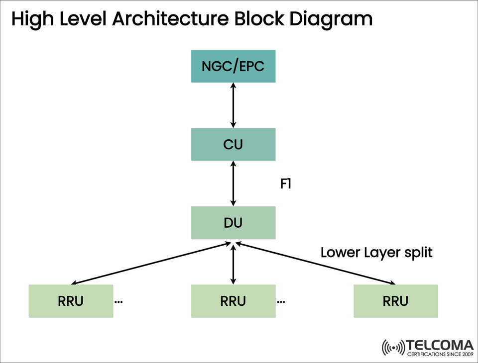
The diagram above is a high level 5G architecture block diagram. It shows how the NGC/EPC, CU, DU and RRU are the functional elements of the RAN stack.
Let’s breakdown the individual components, the interfaces that connect the components, and the reasons for the 5G architecture.
What does the Diagram Highlight?
The diagram highlights the hierarchical structure between the:
NGC/EPC (Next Generation Core / Evolved Packet Core)
CU (Central Unit)
DU (Distributed Unit)
RRU (Remote Radio Unit)
From a RAN perspective, each of these elements have specific functions in the network coating their contributions towards better data performance, mitigating latencies, or enabling flexible deployments within urban and metropolitan contexts.
The Key Elements and Their Functions
- NGC/EPC – Core of the Network
NGC (Next Gen Core): This component is part of 5G SA (Standalone) architecture.
EPC (Evolved Packet Core): This component accommodates both 4G and 5G NSA (Non-Standalone) architecture.
Role: This component configures subscriber management, mobility, session management and inter-networking.
- CU - Central Unit
Location: A CU will typically be located in a regional or central data center.
Function:
Handles non-real-time protocols (Layer 3; part of Layer 2)
Manages control and user plane over F1-C and F1-U
Benefits:
Reduces workload for scaling the network.
Centralised control logic shared across multiple DUs.
- DU - Distributed Unit
Location: More broadly located toward the edge or cell site.
Function:
Handles real-time Layer 1 and 2.
Handles MAC, RLC, the lower layers of PHY.
Communicates with CU via F1 interface.
Benefits:
Reduced latency.
Allows for edge computing.
Improves performance in high-density areas.
- RRU - Remote Radio Unit
Also Known As: RU (Radio Unit) or RRU (in some standards).
Location: Mounted on a tower, on rooftops or on a pole at street level.
Function:
Manages transmission and reception of RF.
Digital to Analog conversion and vice-versa.
Communicates to DU using the lower-layer split (e.g. Option 7.2x in O-RAN). Knowing the interfaces.
Understanding Interfaces
F1 Interface (CU to DU)
Defined by 3GPP.
Separation of Control and User Plane.
F1-C: Control signalling.
F1-U: User data traffic.
CU and DU can be independently scalable and vendor agnostic.
Lower Layer Split (DU to RRU)
Refers to the functional split at layer 1 (PHY layer).
Advantages of this Modular Architecture
Feature Advantage
Functional Disaggregation Efficient load balancing across CU, DU and RRU
Open Interfaces Interoperability across vendors (F1, Open Fronthaul)
Distributed DU Edge Deployment Low latency for URLLC applications
Scalable CU Architecture Controllable centralized CU with flexible user plane capacity scaling
RRU Efficiency Reduces RF tasks and less power consumption typically
Deployment Scenarios
This architecture can fit into various deployment approaches, including:
Urban High-Capacity Sites: DUs and RUs installed at cell sites and CUs at regional data centers.
Private 5-G Networks: On premises CU + DU with local RRU to connect to campus.
Rural Regions: Centralized DU controlling multiple RUs spanning a large area.
Conclusion
The high-level 5G architecture shown in the diagram above shows the movement away from monolithic base stations to modular, disaggregated systems. The separation of CU, DU, and RRU with standardized interfaces, such as F1 and lower-layer splits, enables the operators the following benefits:
Flexibility of deployment
Optimization of cost structures
Support of various use cases (IoT, AR/VR, industry automation)
Understanding this architecture is valuable for all professionals within telecom and who have the responsibility of designing or optimizing 5G networks.
Integration with O-RAN (Open RAN) Architecture
The architecture represented in the diagram is compatible with the Open RAN concept. Open RAN philosophy focuses on openness, modularity, and interoperability across vendor equipment. Here is how the block diagram represents the elements of O-RAN designs:
- Open Interfaces
The F1 Interface (CU to DU) is defined by 3GPP.
The Lower Layer Split Interface (DU ↔ RRU) generally uses an O-RAN standardized option 7.2x allowing multi-vendor deployments.
- Decoupled Components
The CU, DU and RRU may be from different vendors.
Supports Software Defined Networks (SDN) and Network Function Virtualization (NFV).
- Edge and Cloud ready
The CU may run in a regional data center or in the cloud.
The DU can be at the edge for latency-sensitive applications.
The RRU will remain at the radio site, only responsible for RF.
Considerations for Network Engineers for Implementation
Some things to consider when deploying this architecture:
Hardware Considerations
DU servers are probably going to have a real time OS, have DPDK software defined networking capabilities, as well as high throughput NIC's.
CU nodes may be setup as a virtualized platform such as OpenStack or Kubernetes.
RRU's are typically custom hardware but are built to the same standard interfaces for interoperability.
Sync
Precision time sync can be critical especially for Time Division Duplex (TDD) and Massive MIMO.
Would recommend IEEE 1588v2 (PTP) or GPS based versions.
Use Cases
Industry Application Architecture Implications
Smart Manufacturing Robotics, automation, real-time telemetry DU at the edge, CU in either local or cloud
Smart Cities Surveillance, public Wifi, traffic management DU at edge hubs and CU in some central region site
Telecom Operators Better lot and small cells in areas of dense urban coverage DU deployed as distributed element, CU as central, RRU can be flexible on installation
Concluding Remarks The disaggregated 5G architecture (CU, DU, RRU) is proof of concept for modern mobile network future-proofing and the concept of:
Network flexibility
Cloud readiness
Edge computing
Open interfaces that provide vendor diversity, etc.
It is critical for those in telecoms, and engineers, to understand this architecture to deliver great 5G performance for a variety of businesses.