
Initial Attach on E-UTRAN via 5G Core – Complete Call Flow Explained for Telecom Engineers

Initial Attach on E-UTRAN via 5G Core: A Complete Call Flow Breakdown
Moving from 4G LTE to 5G isn't just about faster speeds; it's really about how well the networks can work together. The Initial Attach procedure on E-UTRAN via the 5G Core (5GC) is crucial for getting User Equipment (UE) connected to the network and accessing services, taking advantage of both LTE radio and 5G core features.
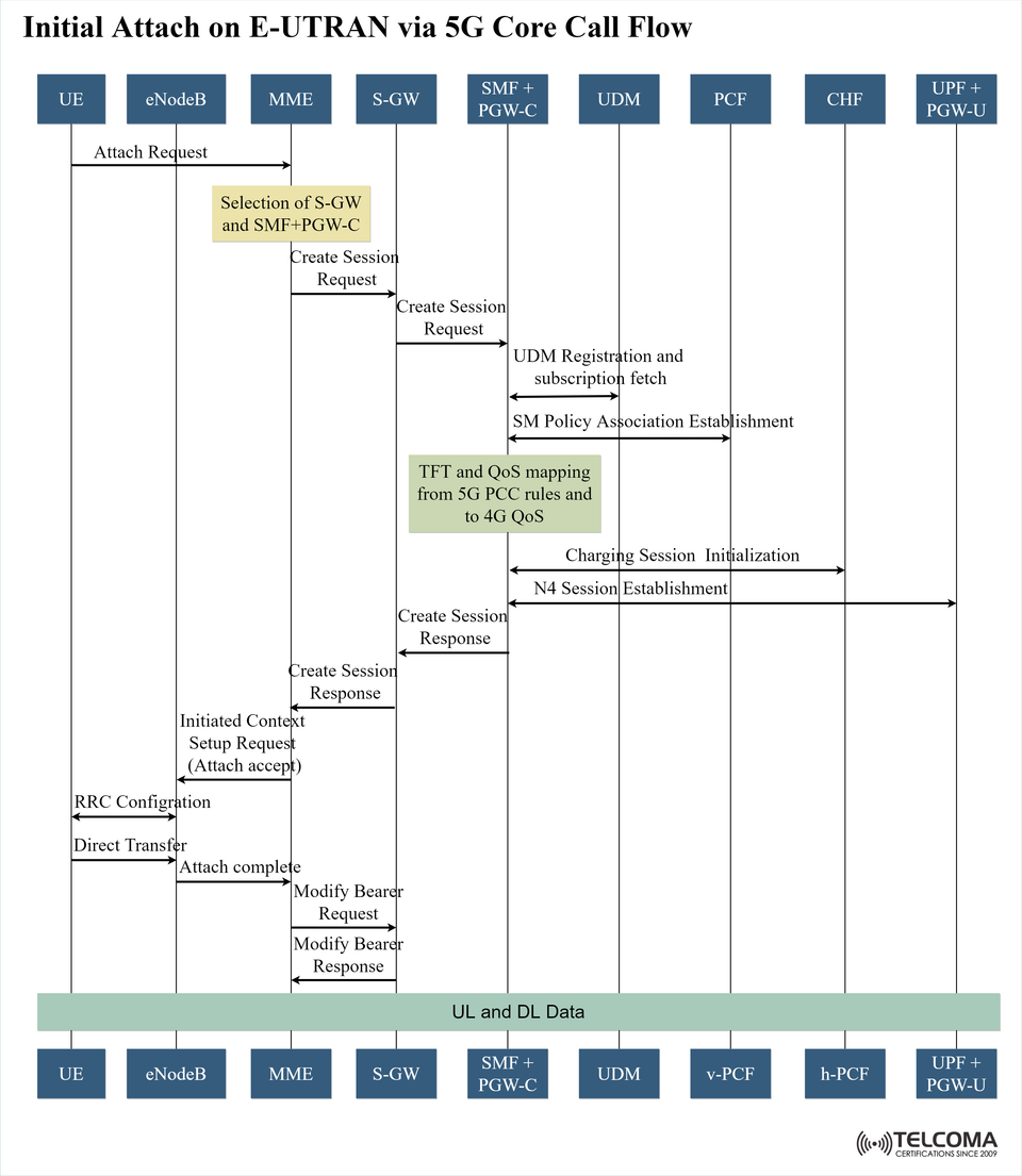
The call flow diagram shows how a UE first connects to an LTE eNodeB while being managed by the 5G Core, which helps ensure that everything is backwards compatible, allowing for a seamless user experience during this transition.
Understanding the Setup
In this context:
Radio Access Network (RAN): LTE E-UTRAN (eNodeB)
Core Network: 5G Core (5GC), with AMF/SMF functions working alongside EPC components for greater interoperability.
Use Case: 4G radio access while leveraging 5G’s policy, QoS, and charging management.
This strategy helps operators keep their existing LTE infrastructure while gradually rolling out 5G Core capabilities.
Key Components in the Call Flow
This process involves coordination among:
ComponentRole in Call FlowUERequests to connect to the networkeNodeBHandles radio signaling for LTEMMEManages the UE context and oversees the attaching processS-GWRoutes and forwards user dataSMF + PGW-CManages session and control in the 5GCUDMStores user subscriptions and profilesPCFProvides policy control and QoS rulesCHFHandles charging functions for billingUPF + PGW-UManages user plane traffic in the 5GC
Step-by-Step Initial Attach Process
Step 1: Attach Request
The UE kicks things off by sending an Attach Request to the eNodeB, which then forwards it to the MME. This request includes the UE’s identity and its capability info.
Step 2: Choosing S-GW and SMF + PGW-C
Next, the MME picks a suitable Serving Gateway (S-GW) and a Session Management Function (SMF) plus the Packet Gateway Control Plane (PGW-C) to anchor the session. This choice depends on factors like location, load balancing, and subscription policies.
Step 3: Create Session Request (MME → S-GW → SMF + PGW-C)
Then, the MME sends out a Create Session Request, which starts setting up the user plane connection to the 5GC.
Step 4: UDM Registration and Subscription Fetch
The SMF reaches out to the Unified Data Management (UDM) to register the UE and get its subscription details, which includes allowed services, data plans, and QoS profiles.
Step 5: Establishing SM Policy Association
The SMF talks to the Policy Control Function (PCF) to get the necessary PCC (Policy and Charging Control) rules. These rules will define QoS parameters and how traffic should be treated during the session.
Step 6: TFT and QoS Mapping
Now, the Traffic Flow Template (TFT) and QoS parameters are mapped from 5G PCC rules to comparable 4G QoS bearers to make sure the LTE radio can enforce the QoS defined by the 5GC.
Step 7: Starting the Charging Session
The Charging Function (CHF) is activated to kick off the data collection for billing purposes.
Step 8: N4 Session Establishment
The SMF sends an N4 Session Establishment message to the UPF, helping to create the user plane route. This sets up the paths for data forwarding.
Step 9: Create Session Response
The SMF + PGW-C sends the session details back through the S-GW to the MME, confirming that the session was successfully created.
Step 10: Context Setup & Attach Acceptance
The MME instructs the eNodeB to set up the UE’s radio bearer with an Initial Context Setup Request, and the UE gets an Attach Accept message.
Step 11: RRC Configuration
The eNodeB performs Radio Resource Control (RRC) configuration to make sure the UE has the right radio parameters for data transfer.
Step 12: Attach Completion
The UE responds with an Attach Complete message.
Step 13: Modify Bearer Procedure
Once attached, the MME can start a Modify Bearer Request to update session parameters or QoS settings if needed.
Step 14: UL and DL Data Transfer
After the attachment is completed, the UE can send and receive user plane traffic, with the 5GC taking care of QoS and policy control while the LTE RAN handles the radio access.
Benefits of the Initial Attach on E-UTRAN via 5GC
Seamless LTE–5G Integration
Reuses LTE radio resources as the transition to a 5G core takes place.
Advanced Policy and QoS Management
Uses 5GC’s dynamic QoS flows, all while still working on LTE radio bearers.
Enhanced Charging and Control
Leverages 5GC’s CHF for more flexible charging options.
Simplified User Experience
Users won't notice a difference in connectivity, even with the data being processed through the 5GC.
QoS Mapping: Connecting 5G Policy to 4G Bearers
A key part of this process is QoS mapping. Since LTE relies on bearer-based QoS while 5G uses flow-based QoS, we need to translate the TFT and PCC rules:
5G QoS ParameterMapped 4G Parameter5QI (5G QoS Identifier)QCI (QoS Class Identifier)ARP (Allocation Retention Priority)Same in LTEGBR/Non-GBRGBR/Non-GBR bearerReflective QoSNot directly supported in LTE
Technical Considerations for Operators
Deployment Needs
Testing for EPC–5GC interoperability.
Compatibility of SMF and MME software with hybrid attach mode.
A policy server that can provide dual-format rules (PCC + legacy EPC).
Potential Challenges
QoS mismatches could lead to performance issues, especially for latency-sensitive applications.
There might be more signaling due to extra SMF and PCF interactions.
Roaming complexities can arise if a visited network doesn’t support 5GC-based attachments.
Troubleshooting Attach Issues
Issue Likely Cause Fix Attach rejected Subscription mismatch in UDM Check UDM profile No QoS enforcement TFT mapping failure Check PCC rule translation Delayed attach High latency in N4 setup Optimize UPF placement Charging errors CHF integration issue Validate SMF–CHF interface
Wrap-Up
The Initial Attach on E-UTRAN via 5G Core process is an essential technology for the shift from LTE to 5G. By enabling legacy LTE radio access to benefit from the superior control, policy, and charging capabilities of the 5G Core, operators can make the most out of their existing infrastructure while also giving customers a better and more consistent experience.
For telecom engineers, grasping this process is crucial—not only for deployment but also for optimizing QoS, minimizing latency, and ensuring accurate billing in real-world 4G–5G hybrid networks.