
LTE Physical Layer and Protocol Stack Explained – NAS, RRC, PDCP, RLC, MAC, and PHY

Understanding the LTE Physical Layer and Protocol Stack
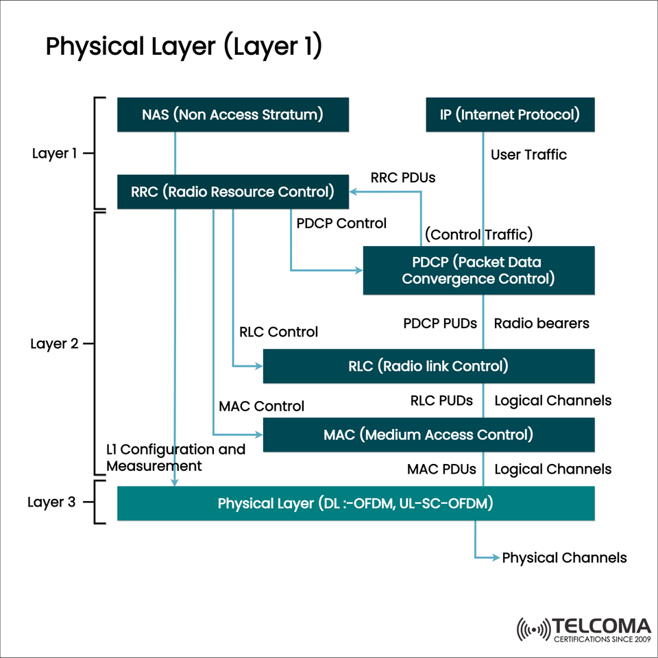
The LTE (Long Term Evolution) protocol stack is really important for mobile broadband networks. It defines how user data and control messages flow between the UE (User Equipment) and the eNodeB. The accompanying image shows the LTE protocol stack, starting with NAS (Non-Access Stratum) at the top and leading down to the physical layer (Layer 1) at the bottom.
Grasping this layered setup is key for telecom engineers, network planners, and anyone interested in boosting LTE performance and troubleshooting issues.
LTE Protocol Stack Overview
You can break down the LTE protocol stack into three main layers:
Layer 3 (Control Plane): Consists of NAS and RRC
Layer 2 (Data Link Layer): Includes PDCP, RLC, MAC
Layer 1 (Physical Layer): Involves PHY (transmission based on OFDM/SC-FDMA)
Each layer has its specific role and interacts with others through defined interfaces and protocols.
Layer 3: Control Plane Protocols
- NAS (Non-Access Stratum)
Definition: NAS is above the access stratum, managing mobility, security, and session management.
Functions:
Authentication and encryption
Bearer creation and release
Attach/Detach procedures
Communication: NAS messages are shared between UE and MME through the RRC and S1-AP layers.
- RRC (Radio Resource Control)
Role: It's the control plane protocol in the E-UTRAN.
Functions:
Connection management: Handles the establishment, reconfiguration, and release of RRC connections.
Mobility: Manages handovers and cell reselection.
Measurement control: Gathers radio measurements (RSRP, RSRQ) from UE.
Security: Distributes keys for ciphering and integrity to lower layers.
Interface: Sends control messages to PDCP and oversees radio bearers.
Layer 2: Data Link Layer Protocols
Layer 2 is split into three sublayers: PDCP, RLC, and MAC.
- PDCP (Packet Data Convergence Protocol)
Main Purpose: Optimizes IP packets for transmission over the air.
Key Functions:
Header compression (using ROHC – Robust Header Compression)
Ciphering and deciphering user plane data
Integrity protection for control plane
Ensures data is delivered in sequence and detects duplicates
Output: Generates PDCP PDUs, which go to RLC for segmentation or concatenation.
- RLC (Radio Link Control)
Functionality: Ensures data is segmented and reliably delivered.
Modes of Operation:
AM (Acknowledged Mode): For reliable data that uses retransmission.
UM (Unacknowledged Mode): For real-time services like VoIP (no retransmission).
TM (Transparent Mode): For broadcasting and control messages.
Role: Converts PDCP PDUs into RLC PDUs, manages retransmissions (ARQ), and keeps data in order.
- MAC (Medium Access Control)
Role: Efficiently allocates radio resources and multiplexes logical channels onto transport channels.
Key Functions:
Scheduling (both uplink and downlink)
HARQ (Hybrid Automatic Repeat Request) for error correction
Multiplexing/demultiplexing data from various bearers
Handles data stream priority
Output: Creates MAC PDUs that are sent to the physical layer.
Layer 1: Physical Layer (PHY)
The physical layer serves as the backbone of LTE communication, taking charge of the actual modulation, transmission, and reception of signals through the air.
Key Functions of the PHY Layer:
Modulation and Coding: Uses OFDM (Orthogonal Frequency Division Multiplexing) for downlink and SC-FDMA for uplink.
Channel Coding: Applies turbo coding for error resilience.
Resource Mapping: Maps data onto time-frequency resource elements.
MIMO Processing: Facilitates spatial multiplexing and beamforming.
Measurement Reporting: Supplies radio measurements to higher layers (used by RRC).
Physical Channels:
PDSCH (Physical Downlink Shared Channel): Carries user data.
PDCCH (Physical Downlink Control Channel): Sends out scheduling grants.
PUSCH/PUSCH: Transmits uplink data and control information.
Synchronization Channels (PSS/SSS): Used for cell search and synchronization.
Control vs. User Plane Data Flow
The diagram illustrates how control traffic (NAS, RRC) and user plane traffic (IP packets) navigate different paths:
Plane | Protocols | Purpose
Control Plane | NAS → RRC → PDCP → RLC → MAC → PHY | Manages signaling, mobility, and bearer setup
User Plane | IP → PDCP → RLC → MAC → PHY | Delivers user data (voice, video, internet)
This separation helps LTE manage signaling and data independently, ensuring better performance.
Why This Architecture Matters
Getting a handle on LTE's protocol layers is essential because:
Network Optimization: Engineers can adjust scheduling, HARQ, and bearer settings for better performance.
Troubleshooting: Pinpointing the layer causing packet loss can help fix issues quickly.
Quality of Service (QoS): Correct bearer mapping ensures low latency for VoLTE and high throughput for data.
Security: Ciphering and integrity protection happen at the PDCP layer, blocking unauthorized access.
Real-World Applications
VoLTE Calls: Use PDCP for header compression and RLC AM for reliability.
Streaming: Typically employs RLC UM to cut down on delay.
IoT over LTE: Utilizes lightweight PDCP and MAC scheduling for energy-efficient transmissions.
Carrier Aggregation: Needs coordination at the MAC layer across multiple component carriers.
Conclusion
The LTE protocol stack is well-structured, with each layer collaborating to ensure reliable, fast, and secure communication. From NAS and RRC for signaling, through PDCP, RLC, and MAC for data processing, all the way down to the physical layer, each component has its own significance.
For telecom experts, mastering this framework is vital for network design, performance tweaks, and troubleshooting. As we move towards 5G, many of these core principles will still be in play, with NG-RAN and NR adopting similar layered setups but with enhanced flexibility and reduced latency.