
LTE Radio Access Network Interface: S1-c, S1-u, and X2 Explained

The Importance of RAN Interfaces in LTE
The Radio Access Network (RAN) is crucial for mobile communications, acting as the link between user devices (UEs) and the core network. In LTE (Long Term Evolution), the RAN is centered around the eNodeB (Evolved Node B), which takes care of both the radio access and baseband processing tasks.
But the eNodeB doesn’t operate in isolation. It needs to interact with the core network (Evolved Packet Core, EPC) and other neighboring eNodeBs to maintain smooth user mobility, effective signaling, and data transport.
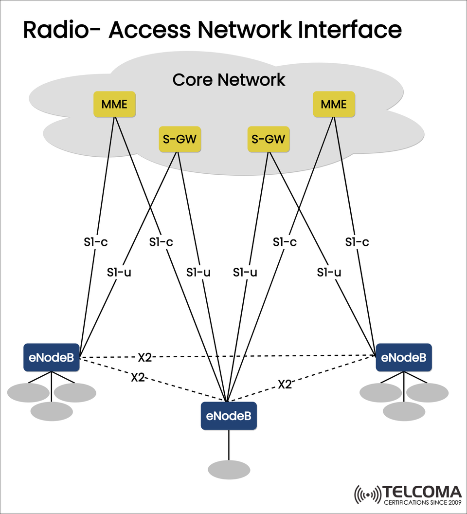
This is where the RAN interfaces come into action. The diagram uploaded shows the two main interfaces in LTE RAN:
S1 Interface (S1-c and S1-u) → Connects eNodeBs to the EPC.
X2 Interface → Links neighboring eNodeBs directly.
Together, these interfaces handle session management, mobility, and data transfer throughout LTE networks.
LTE Radio Access Network Architecture
Before we dive into the interfaces, let’s quickly review the primary components of the LTE RAN:
eNodeB (Evolved Node B):
Manages radio resources, scheduling, mobility, and signaling tasks.
Communicates directly with UEs.
Links to the EPC through S1 interfaces and connects to other eNodeBs via X2.
Core Network (Evolved Packet Core, EPC):
MME (Mobility Management Entity): Deals with signaling, authentication, and mobility management.
S-GW (Serving Gateway): Routes user data between the eNodeB and the Packet Data Network Gateway (P-GW).
P-GW (Packet Data Network Gateway): Allows IP connectivity to external networks (like the internet or IMS).
Now, let’s look closer at the interfaces that connect these components.
S1 Interface: Linking eNodeB to the Core Network
The S1 interface is what connects each eNodeB to the EPC. It's divided into two logical sections:
S1-c (Control Plane):
Connects eNodeB to MME.
Used for signaling and control functions.
Manages tasks like:
UE attachment and registration.
Authentication and security setup.
Bearer (session) establishment.
Handover signaling (when a user transitions to a new eNodeB).
S1-u (User Plane):
Connects eNodeB to S-GW.
Handles actual user data transfer (like internet packets, video streaming, voice over LTE).
Uses GTP-U (GPRS Tunneling Protocol – User plane).
Ensures uninterrupted data delivery even as UEs move between cells.
Key Features of the S1 Interface
Flexibility: An eNodeB can connect to various MMEs and S-GWs for backup and load balancing.
Scalability: Supports thousands of UEs at the same time.
Separation of Planes: Control and user traffic travel via separate routes, improving efficiency.
X2 Interface: Connecting eNodeBs to Each Other
While the S1 interface manages communication with the core network, the X2 interface connects eNodeBs directly.
Purpose: Allows coordination, mobility, and load management without needing to go through the EPC.
Connections: Each eNodeB can form X2 links with neighboring eNodeBs.
Functions of the X2 Interface
Handover Management:
When a UE moves from one eNodeB’s coverage area to another, the X2 interface enables X2-based handover.
This reduces the signaling load on the MME and ensures quicker, smoother mobility.
Load Balancing:
eNodeBs can share load information.
UEs may be directed to less congested neighboring cells.
Interference Management:
Neighboring eNodeBs coordinate transmission power and scheduling to minimize interference.
Error Handling and Recovery:
Helps maintain communication during link failures or congestion.
Comparison: S1 vs. X2 Interface
FeatureS1 InterfaceX2 Interface
Connectivity eNodeB ↔ EPC (MME/S-GW)eNodeB ↔ Neighbor eNodeB
PlanesS1-c (control), S1-u (user)Single (control + coordination)
Functions UE attachment, session setup, signaling, user data transport Handover, load balancing, interference management
Dependency Requires EPC involvement Direct eNodeB-to-eNodeB communication
Efficiency Centralized Distributed, reduces EPC load
Example: UE Mobility Across eNodeBs
Picture a user streaming a video while strolling through town:
Initial Connection:
UE connects to the network via S1-c with MME.
Data is sent through S1-u (via S-GW).
Approaching New Cell:
The serving eNodeB notices a drop in signal strength.
It communicates with the target eNodeB through X2 to prepare the necessary resources.
Handover Execution:
The UE is smoothly transitioned to the new eNodeB using X2 handover.
If X2 isn't available, the handover uses S1-c signaling with the MME instead.
Data Continuity:
User data continues flowing through S1-u without any noticeable interruption.
That's how LTE ensures smooth mobility and consistent service quality.
Importance of RAN Interfaces in LTE Evolution
RAN interfaces are key to LTE’s efficiency and scalability. They bring several advantages:
Lower Latency: X2 handovers lessen core network involvement.
Enhanced Reliability: Multiple S1 connections provide backup.
Optimized Resource Utilization: Load balancing helps distribute traffic across cells.
Support for a Massive Number of UEs: Efficient signaling allows for scaling up to millions of devices.
Additionally, these interfaces have set the stage for 5G NR architecture, applying similar principles through NG interfaces and Xn interfaces.
Challenges and Considerations
Even though they have many benefits, RAN interfaces come with their own set of challenges:
Deployment Complexity: Multiple connections necessitate careful planning of the network.
Interoperability Issues: Different vendors’ eNodeBs may have compatibility challenges.
Security Concerns: Interfaces need to be secured against signaling and data plane attacks.
Scalability Pressures: As IoT and data demands grow, S1-u can become a bottleneck.
Summary Table: LTE RAN Interfaces
Interface Connects Purpose
S1-ceNodeB ↔ MME Signaling, session setup, mobility management
S1-ueNodeB ↔ S-GWUser data transport
X2eNodeB ↔ eNodeB Handover, load balancing, coordination
Conclusion
The Radio Access Network (RAN) interfaces in LTE—S1-c, S1-u, and X2—act like unseen highways that keep communication flowing smoothly between user devices, eNodeBs, and the core network.
S1-c and S1-u connect the eNodeB to the EPC for signaling and user data transfer.
X2 enables direct communication between eNodeBs for efficient handovers and resource optimization.
By separating control and user planes and allowing for distributed coordination through X2, LTE provides the low latency, high reliability, and seamless mobility that users enjoy daily.
For professionals in telecommunications, understanding these interfaces is vital for designing, optimizing, and troubleshooting LTE networks. And for enthusiasts, it offers an intriguing look into how mobile connectivity remains smooth while we stream, browse, and communicate on the go.