
LTE Uplink L2 Protocol Structure Explained: PDCP, RLC, and MAC Layers

The Importance of Uplink L2 Protocols
In LTE, the uplink serves as the path for communication from the User Equipment (UE) to the eNodeB (base station). To maintain reliable data transfer, LTE relies on a layered protocol stack.
The L2 (Layer 2) protocol structure is key in managing:
Error correction and retransmission
Segmentation and reassembly of data
Service prioritization
Security and encryption
Resource allocation and scheduling
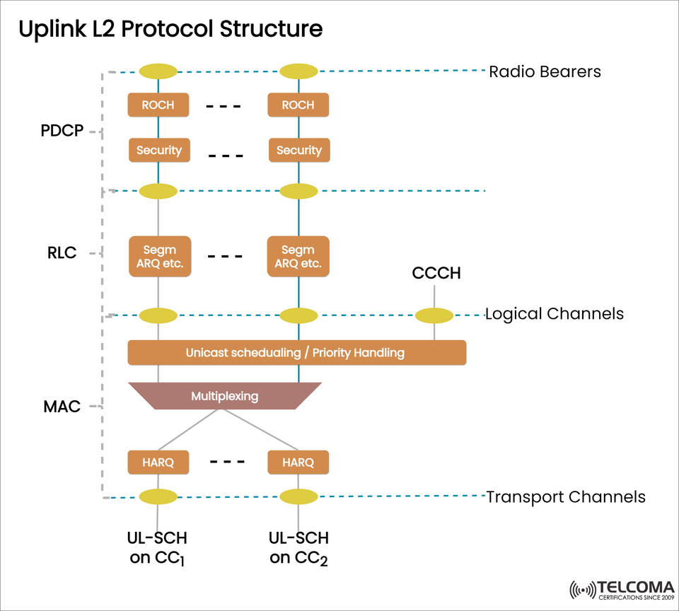
The diagram uploaded illustrates how the PDCP, RLC, and MAC layers work together with logical and transport channels to facilitate smooth uplink communication. Let’s dive into each component of this structure.
Overview of the LTE Protocol Stack
The LTE protocol stack is broken down into three layers:
Layer 1 (Physical Layer): This is all about handling the actual radio transmissions.
Layer 2 (Data Link Layer): It manages error handling, retransmission, and ensures data integrity.
Layer 3 (Network Layer): This includes RRC (Radio Resource Control) for signaling.
Our main focus is on Layer 2 (L2), which sits between the upper layers' IP packets and the physical transmission over the radio interface.
The Three Sub-Layers of LTE Uplink L2
- PDCP (Packet Data Convergence Protocol)
Functions: * Header compression (using ROHC – Robust Header Compression). * Security (encryption and integrity protection). * Ensures packets are delivered in sequence.
Why It Matters: Without PDCP, the IP headers (IPv4 or IPv6) would take up too much bandwidth. Plus, security ensures that the data is encrypted before it’s sent out.
In the Uplink: * ROHC helps reduce overhead for more efficient transmission. * Security ensures user data confidentiality and integrity.
- RLC (Radio Link Control)
Functions: * Segments and reassembles data. * Uses ARQ (Automatic Repeat reQuest) for correcting errors. * Can concatenate smaller packets.
Modes of Operation: * TM (Transparent Mode): Minimal processing, mainly for control channels. * UM (Unacknowledged Mode): Offers error detection but doesn’t do retransmission. * AM (Acknowledged Mode): Guarantees reliable delivery with retransmission.
In the Uplink: The RLC takes PDCP packets and breaks them into smaller pieces that fit what the MAC has allocated for transport blocks. If there are errors, ARQ mechanisms trigger retransmissions.
- MAC (Medium Access Control)
Functions: * Manages multiplexing and demultiplexing of logical channels. * Handles scheduling and prioritizing tasks. * Uses HARQ (Hybrid Automatic Repeat reQuest) for quick retransmissions. * Maps logical channels to transport channels.
In the Uplink: * MAC collects data from various logical channels. * It applies scheduling and priority decisions. * Combines data into transport blocks. * HARQ ensures resilience against errors with minimal delays in retransmissions.
Logical and Transport Channels in the Uplink
The uplink logical channels (like CCCH, DCCH, DTCH) carry different types of information. These are mapped to transport channels, mainly:
UL-SCH (Uplink Shared Channel): This is the primary channel for user data and control information.
RACH (Random Access Channel): Used for initiating a connection.
The diagram shows UL-SCH on CC1 and CC2, indicating Carrier Aggregation where multiple component carriers are utilized to increase uplink throughput.
Detailed Walkthrough of the Uplink L2 Protocol Structure
Let’s track the flow of data from the application down to physical transmission:
Application Layer (IP packets) * Creates user data (like video uploads or voice). * Packets then move down to the PDCP layer.
PDCP Layer * Uses ROHC to compress headers. * Ensures security through encryption. * Transfers PDCP Service Data Units (SDUs) to RLC.
RLC Layer * Segments or combines PDCP SDUs into RLC Protocol Data Units (PDUs). * Provides error correction with ARQ in AM mode. * Delivers RLC PDUs to MAC.
MAC Layer * Takes care of scheduling and priority handling (deciding which logical channels receive resources). * Performs multiplexing, blending multiple logical channels into transport blocks. * Carries out HARQ for error recovery. * Sends data over UL-SCH (using one or more component carriers).
Transport Channels → Physical Layer * UL-SCH is assigned to PUSCH at the physical layer. * Data is transmitted over the air to the eNodeB.
Example Scenarios
- Initial Access
The UE sends a connection request using CCCH → RLC (TM) → MAC → UL-SCH → PUSCH.
- File Upload
Data flows through PDCP (ROHC + Security) → RLC (AM) → MAC (HARQ) → UL-SCH → PUSCH.
- Carrier Aggregation
When using multiple component carriers, data is distributed across UL-SCH on CC1 and CC2, boosting overall throughput.
Key Functions by Layer (Summary Table)
Layer Functions in Uplink Example Features PDCP Header compression, security, in-sequence delivery ROHC, ciphering RLC Segmentation, error correction, retransmission ARQ, AM/UM modes MAC Scheduling, multiplexing, error correction HARQ, priority handling Transport Main uplink data channel UL-SCH, RACH Physical Radio transmission PUSCH, PRACH
Why Uplink L2 Structure is Critical
Efficiency: It cuts down overhead with ROHC.
Security: It guarantees encrypted and authenticated communication.
Reliability: The error correction (ARQ, HARQ) strengthens robustness.
Flexibility: It accommodates various services with prioritization in scheduling.
Scalability: Carrier aggregation enhances throughput for next-gen LTE and 5G.
Challenges in Uplink L2
Even though it’s well-designed, the uplink L2 does face some challenges:
Scheduling Delays: Resource allocation relies on eNodeB scheduling.
Error Recovery Overheads: ARQ and HARQ retransmissions can add to latency.
Interference: Incrowded networks can result in collisions on RACH.
Battery Life Impact: Enhanced security and retransmissions can drain UE batteries.
Evolution in 5G NR
5G takes the uplink L2 framework further by introducing:
Grant-Free Uplink: This cuts down latency by eliminating the need for scheduling requests.
Flexible HARQ Configurations: More efficient retransmissions.
PDCP Enhancements: Allows for dual connectivity between LTE and 5G.
MAC-Level Improvements: Better scheduling for URLLC and massive IoT.
So, LTE’s uplink L2 is really the groundwork for designing the uplink protocol in 5G NR.
Conclusion
The LTE uplink L2 protocol structure is a layered framework that guarantees efficient, secure, and reliable communication from the UE to the eNodeB.
PDCP compresses headers and secures the data.
RLC guarantees error-free segmentation and retransmission.
MAC is responsible for scheduling, multiplexing, and implementing HARQ for resilience.
Transport channels (UL-SCH) transmit the data to the physical layer.
With its well-structured design, the LTE uplink can handle everything from basic signaling to high-speed data applications, and it paves the way for future advancements in 5G NR.
For those in telecom, getting a solid grip on the uplink L2 protocol stack is crucial for optimizing networks, solving issues, and ensuring a top-notch experience for users.