
LTE vs 5G NR Control Structure: Understanding CORESET and Bandwidth Parts

LTE vs 5G NR Control Structure: A Look at CORESET and Bandwidth Parts
As we move through the different generations of mobile communication, a big goal is to make systems more flexible, scalable, and efficient. LTE (Long Term Evolution) set a solid foundation with its OFDMA-based framework for high-speed broadband. But with the rise of 5G NR (New Radio), we really needed a system that could handle more spectrum agility and dynamic resource allocation.
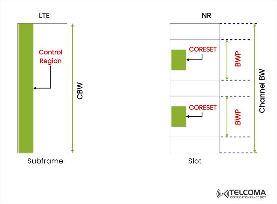
The image you uploaded does a great job of visually comparing LTE’s fixed control region against the more adaptable CORESET (Control Resource Set) and BWP (Bandwidth Part) concepts we see in 5G NR.
- Overview of LTE Control Region
In LTE, the control region takes up a set portion of each subframe, which is used for downlink control information (DCI) like scheduling assignments and hybrid-ARQ acknowledgments.
How LTE Looks:
Each LTE subframe lasts 1 millisecond (ms).
The control region is at the start of the subframe, as seen in the image.
The Control Bandwidth (CBW) covers the whole channel bandwidth, meaning control info gets sent across all the available subcarriers.
Main Features:
Fixed Size: The control region has a predetermined, static size.
Limited Flexibility: Every user has to decode control information over the full bandwidth, even if they’re only using a small part of it.
High Power Usage: UEs have to keep an eye on the entire channel bandwidth at all times.
Simple Layout: It’s straightforward to implement and works well for uniform bandwidths and static setups.
While LTE was efficient for 4G’s more stable network environment, it didn’t quite have the scalability and flexibility needed for 5G’s varied applications, including IoT, enhanced Mobile Broadband (eMBB), and Ultra-Reliable Low-Latency Communication (URLLC).
Moving to 5G NR: A More Adaptable Design
5G NR is built to manage a wide range of frequency bands, bandwidths, and use cases — from low-band IoT connections to mmWave gigabit links. To accomplish this, NR revamped the control plane by bringing in two new ideas:
CORESET (Control Resource Set)
BWP (Bandwidth Part)
These developments replaced LTE’s fixed control region with a more adaptable, energy-efficient, and scalable control structure.
What CORESET Means in 5G NR
Defining CORESET
CORESET (Control Resource Set) is a set of Physical Resource Blocks (PRBs) and OFDM symbols designated for transmitting downlink control information (DCI). Basically, it's like the NR version of LTE’s control region but with much more flexibility.
In the diagram, you can see CORESET highlighted as the green-shaded blocks within each slot.
Characteristics of CORESET:
Configurable Size: Operators can decide on the number of symbols (1–3) and how many PRBs to include.
Flexible Positioning: Unlike LTE, CORESET can be placed anywhere within the channel bandwidth.
Multiple CORESETs: A UE can operate with several CORESETs for different tasks (like initial access or scheduled traffic).
Dynamic Scheduling: Control and data areas are separate, allowing for different configurations based on service type.
Technical Insights:
Parameter | LTE Control Region | NR CORESET
Location: Fixed at subframe start | Flexible, anywhere in channel
Bandwidth: Full channel bandwidth | Configurable (subset of bandwidth)
Number of Symbols: Fixed (1–3 OFDM symbols) | Configurable (1–3 OFDM symbols)
Reconfiguration: Static | Dynamic and UE-specific
How CORESET is Used:
CORESET#0: For initial access (common search space).
CORESET#1, #2: For dedicated control signaling to certain UEs.
This adaptability helps NR efficiently cater to diverse services using the same carrier bandwidth — like eMBB users and IoT devices — without wasting any spectrum.
What’s BWP?
Defining Bandwidth Part
A Bandwidth Part (BWP) is a subset of the total channel bandwidth where a UE operates. Instead of making devices check the whole bandwidth, 5G lets them focus on a smaller segment known as a BWP.
In the image, each BWP is shown as a segment of the overall Channel Bandwidth (BW), with one or more CORESETs included.
BWP Features:
Each carrier can have up to four BWPs configured per UE.
Only one BWP can be active at a time.
A BWP sets parameters like subcarrier spacing, cyclic prefix, and numerology.
Benefits of BWP:
Energy Saving: UEs only need to decode within their active BWP, cutting down on power use.
Flexibility: Different BWPs can be set up for various services or QoS needs.
Scalability: Handles a broad array of devices, from budget IoT sensors to high-end smartphones.
Example:
BWP1 (narrow): For low-data-rate IoT communication to conserve power.
BWP2 (wide): Activated for high-throughput tasks like video streaming or 5G URLLC.
LTE vs 5G NR: A Quick Comparison
Feature | LTE | 5G NR
Control Structure: Control Region (Fixed) | CORESET (Flexible)
Bandwidth Allocation: Entire channel bandwidth | Configurable via BWP
UE Power Efficiency: Lower (full bandwidth monitoring) | Higher (limited BWP operation)
Reconfigurability: Static | Dynamic
Spectrum Efficiency: Moderate | Very high
Use Cases: Mobile broadband | eMBB, URLLC, mMTC
Numerology: Fixed (15 kHz) | Flexible (15–240 kHz)
5G’s control design is modular, meaning it can adapt dynamically based on traffic type, spectrum availability, and device capabilities.
Benefits of CORESET and BWP in 5G NR
- Better Spectrum Efficiency
CORESET’s ability to occupy just part of the channel means unused bandwidth can be freed up for data transmission, enhancing overall use.
- Reduced Device Complexity
Low-cost IoT devices can operate in narrow BWPs, making RF design simpler and extending battery life.
- Dynamic Resource Management
Operators can change active BWPs depending on user demand, network traffic, or movement patterns.
- Multi-Service Support
Various CORESETs and BWPs allow for the simultaneous handling of different service types — like ultra-low-latency industrial links alongside high-capacity eMBB connections.
- Improved Coverage and Flexibility
Operators can tweak CORESET placement to maximize control signaling coverage, particularly in multi-beam or mmWave setups.
A Real-World Example
Imagine a 5G network functioning over a 100 MHz channel bandwidth:
A smartphone in eMBB mode might use BWP = 80 MHz with CORESET#1 for high-speed control.
A smart sensor could stick to BWP = 10 MHz with CORESET#0 for low-data, efficient operation.
The gNB can switch between these setups based on the service type and radio conditions.
This kind of adaptive operation isn’t possible with LTE, but it’s a standard feature in 5G NR.
- Key Takeaways
LTE’s Control Region was fixed and simple but not very flexible.
5G NR’s CORESET brings in dynamic and adjustable control regions.
BWP enables per-UE bandwidth adjustments, leading to better energy and spectral efficiency.
Together, CORESET and BWP are foundational for 5G NR’s adaptable and scalable radio interface.
Conclusion
The shift from LTE to 5G NR represents a significant move from rigid, one-size-fits-all control structures to a flexible, adaptive radio design. With CORESET and BWP, 5G NR can effectively manage a variety of devices, frequency bands, and deployment situations — whether it's low-power IoT nodes or high-speed mmWave users.
By uncoupling control signaling from fixed bandwidth and allowing for per-user bandwidth allocation, 5G NR strikes a great balance between efficiency, scalability, and energy optimization.
In short, LTE’s Control Region paved the way for CORESET and BWP in 5G NR to take off.