
LTE vs 5G QoS Architecture: Detailed Comparison and Key Differences

A Comparison of LTE and 5G Quality of Service Architecture
Quality of Service (QoS) is essential for mobile networks because it provides the terms under which voice, video, and data traffic will be prioritized and managed in the network. The migration from LTE (4G) to 5G in evolution brought differences in QoS architecture from EPS bearers to QoS flows.
This diversity adds more flexibility, decreases latency, and accommodates more services options in next-generation networks.
QoS Architecture LTE (4G)
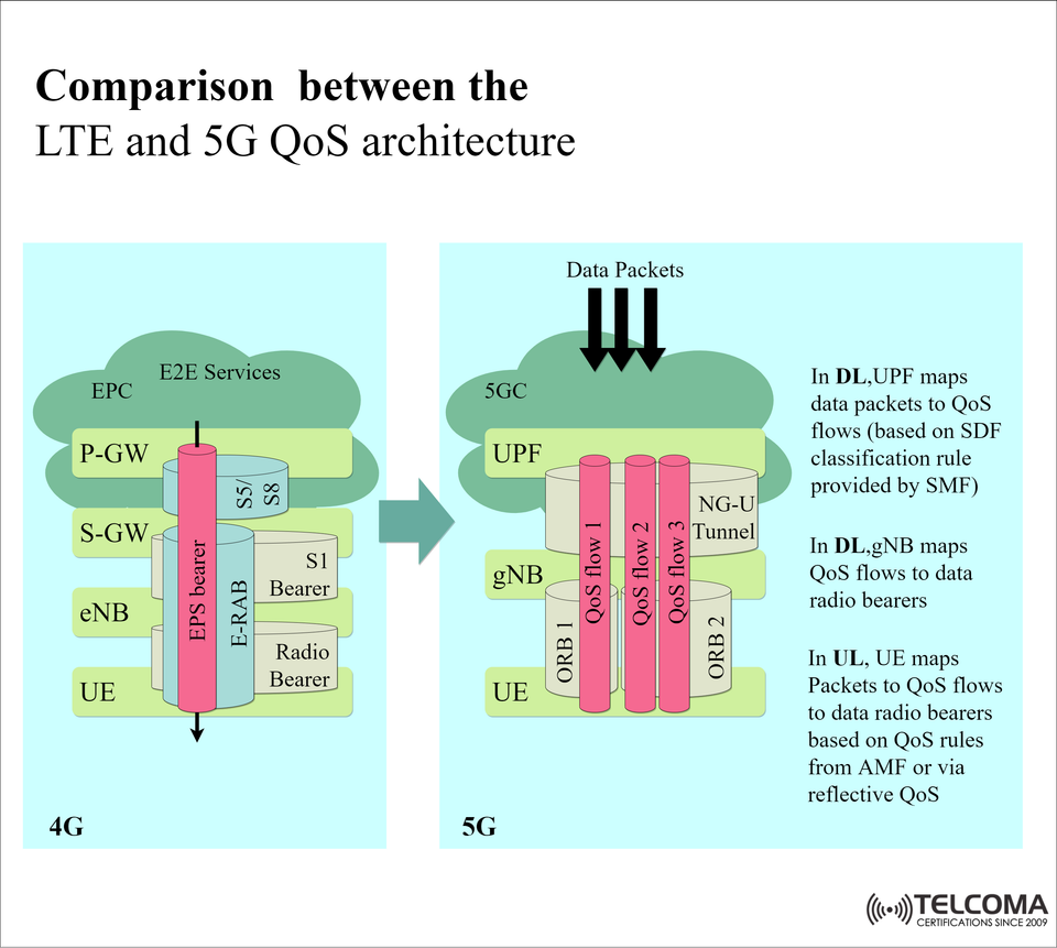
In LTE, QoS architecture is expressed in bearers that provide each user a dedicated data path with QoS characteristics for how QoS is delivered to both the user and the services they are accessing.
Key Components LTE QoS
Evolved packet core (EPC) the core network (consists of the P-GW (packet gateway) and S-GW (serving gateway)).
eNB (evolved NodeB) base station that, in addition to the radio communication aspects also provides some forms of mobility handling.
EPS bearer end-to-end logical path through which packet data is carried, and it is also backed with QoS conditions that have been determined by the subscriber user's context and the services that the user is accessing.
E-RAB (E-UTRAN Radio Access Bearer) radio access path from the EPS bearer.
Radio bearer actual link over the air interface.
LTE QoS Mapping for LTE
UE (user equipment) initiates a connection via EPS bearer, this is then mapped under an S1 bearer in the core network and thus to radio bearer over the air interface.
QoS Architecture with 5G
5G is characterized by replacing the fixed bearer concept with QoS flows which can provide a lot more flexibility in how QoS can be used now.
5G QoS – Key Elements:
UPF (User Plane Function): Responsible for packet forwarding and general QoS flow classification.
gNB (Next-Generation NodeB): The 5G equivalent of a base station, which maps QoS flows to radio resources.
QoS Flow: The smallest 5G QoS granularity that is identifiable by a QoS Flow Identifier (QFI).
ORB (Data Radio Bearer in 5G): Carries the QoS flows across the air interface.
QoS Mapping in 5G:
Downlink (DL) data packets: The UPF maps the UL data packets into QoS flows using Service Data Flow (SDF) classification rules provided by the SMF. The gNB maps QoS flows to radio bearers.
Uplink (UL) data packets: The UE maps data packets into QoS flows, and maps those to a radio bearer based on QoS rules from the AMF or reflective QoS.
LTE vs 5G QoS Architecture – Key Differences
Feature LTE (4G) 5G
QoS Granularity EPS Bearer QoS Flow
Mapping Process EPS bearer → S1 bearer, then to Radio bearer QoS flow → Data Radio Bearer (ORB)
Core Network Elements P-GW, S-GWP UPF
Radio access node eNB gNB
Flexibility Standardized bearer types as configured Highly flexible, per-service or per-application flows.
Latency Optimization Less granularity Optimized through edge deployment X UPF routing
Control signaling Bearer setup or modification QoS flow rules received from SMF/AMF.
Reasons Why 5G QoS is More Advanced:
Service-specific optimization: Each application (AR/VR, IoT, etc...) can have their own QoS flow.
Dynamic allocation: QoS flows can be created, modified, and/or terminated in real-time.
Reduced signaling overhead: No need to create a full bearer for each service.
Reduced latency: UPF located at the edge of the network leads to greater responsiveness.
Conclusion
The transformation from EPS bearers in LTE to QoS flows in 5G is a huge step forward in terms of function, flexibility, and customizing services. The 5G architecture allows operators to customize and improve QoS at a per-application level, and efficiently meet diverse modern services' needs (i.e. massive IoT, mission-critical, enhanced mobile broadband).
Essentially, LTE built the QoS model, while 5G redefines it for the future.
A Closer Look: QoS Flow vs EPS Bearer
- EPS Bearer In LTE
Static: Once established, bearers have defined QoS items (QCI, ARP, GBR/Non-GBR).
One service per bearer: Usually, all packets in a bearer have same QoS.
End to end path: From UE, through eNB, S-GW, P-GW, to outside network. - QoS Flow within 5G specifications
Dynamic nature - Can be created, modified or deleted on-demand. - Multiple services per session - Each service/application can have its own QoS Flow within the same PDU Session.
- Per-packet Control - Packet classification based on Service Data Flow (SDF) rules defined by the SMF.
Example Deployment Scenarios
Scenario 1: Streaming Video in LTE vs 5G
-LTE: The video service is using a dedicated EPS bearer with a specified QCI for guaranteed bit rate.
-5G: The same service is carried using a dedicated QoS Flow with GBR and Latency parameters, dynamically controlled relative to the network load.
Scenario 2: Autonomous Vehicle Communication
-LTE: Limited flexibility to deal with ultra low latency requirements; may require a separate bearer to be configured.
-5G: URLLC specific QoS Flow that ensures millisecond level latency while being dynamically prioritized over other traffic on a per packet basis.
Scenario 3: IoT Sensor Network
-LTE: Using Non-GBR bearers, all devices have similar QoS unless manually configured.
-5G: Each sensor type can have its own dedicated QoS Flow suited to its own data pattern (e.g., delay-tolerant vs. real-time alerts).
A comparison of LTE & 5G QoS - In brief
Parameter LTE QoS (EPS bearer) 5G QoS (QoS Flow)
QoS Entity EPS Bearer QoS Flow (QFI)
Concluding remarks
Moving from EPS bearers in LTE to QoS flows in 5G represents a fundamental change in the design of mobile networks. It allows for:
Service level customizations that can be made dynamically and with real-time inputs.
The most efficient use of resources in a network.
New applications that rely on low latency and ultra-high reliability.
For operators, understanding how to leverage 5G QoS architecture is not simply about replacing previous systems; it requires a rethinking of how services are delivered in an application aware, customer focussed way.