Mobility Optimized Handover in 5G: Conventional DU vs CU/DU Split Architecture

📶 Mobility Optimized Handover in 5G Networks
Handover performance is key to achieving the best user experience in mobile networks. The 5G architecture has introduced CU/DU architectures which allow better mobility procedures than when a centralized DU architecture is in use. This blog post evaluates both approaches, with the goal of optimizing inter-gNB handovers.
🧠 What Is An Inter-gNB Handover?
An inter-gNB handover occurs when a user device moves from one next-generation NodeB (gNB) to another. The inter-gNB handover process includes several complex signaling and message steps, rerouting of user data, and updating of radio level control parameters.
📉 Disadvantages of Centralized DU Architecture
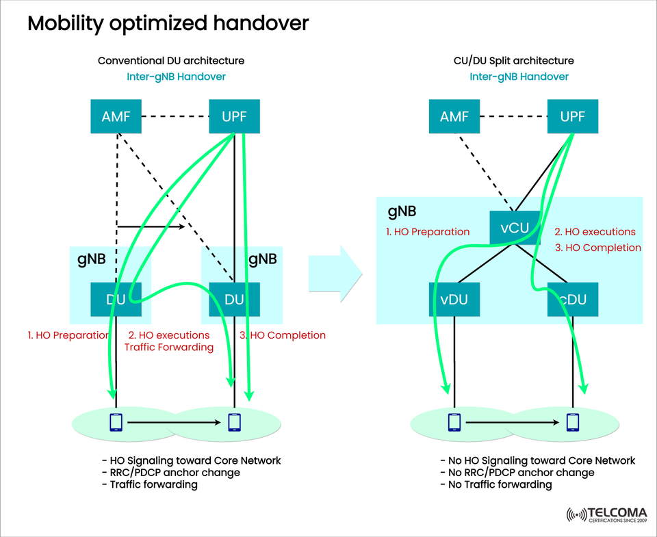
In the original 5G architecture with centralized DUs, the overall handover process consists of:
Handover Preparation: The source DU will trigger the initial handover process through the AMF (Access and Mobility Management Function).
Handover Execution and Traffic Forwarding: Traffic forwarding occurs from the source DU to the Te target DU.
Handover Completion: After a signaling process, the user is formally attached to the new DU.
The above process comes with the following challenges:
High signaling load towards the core network.
Change in RRC and PDCP anchor points.
Higher latency in the handover process attributed to traffic forwarding.
🧩 Deep Dive into Architecture:
Clarifying Key Roles 1. AMF (Access and Mobility Management Function) The AMF is responsible for UE registration, reachability, and mobility. In the traditional architecture, this role has maximum participation during the handover functionality.
- UPF (User Plane Function) Anchored user data traffic. In traditional DU architectures, UE user data traffic must be forwarded during the handover, therefore adding latency.
- CU (Centralized Unit) CU-CP: Responsible for control plane functions, inclusive of mobility control, and RRC signalling. CU-UP: Anchors user plane traffic in a scalable manner. In split architecture the CU-UP role would be tied to the users traffic deferred until handover.
- DU (Distributed Unit) Responsible for lower layer RAN functionality to the UE (e.g., MAC, RLC, PHY). All vDU or cDU in a split architecture only require localized radio functions, therefore transition is more streamlined.
🛰️ Relevance: Physical Impacts
The optimized handover in operation through the CU/DU split directly led to supporting in emerging applications the likes of:
Massive IoT (mMTC): While mobility is low, mMTC devices require a scalable control plane.
Fixed Wireless Access (FWA): High volume of user traffic, therefore a resilient user plane is required.
Autonomous Vehicles and URLLC: Both require ultra-low-latencsie and highly seamless handover with zero packet loss.
🛠️ Important considerations to implement a shift for this Architecture Desirably:
Consolidated orchestration system (e.g., SDN/NFV systems)
Synchronizing CU and DU layers
Sufficient latency within the backhaul layer to maintain DU
📊 Future Trends and Evolution
As 5G continues its journey to 5G-Advanced and beyond:
RAN Intelligent Controllers (RICs) will allow for dynamic CU/DU coordination.
Artificial intelligence-driven mobility management means further delay to handover failure.
Multi-access Edge Computing (MEC) will align with CU/DU splits to bring the access services closer to the end-user.
🔚Final Thoughts
Mobility-optimized handover is no longer a privilege but a must-have requirement for modern service-driven 5G networks. The CU/DU split form factor streamlines the handover process while laying the groundwork for cloud-native, scalable and resilient mobile services infrastructure.
Limiting core network involvement and clean user/control anchoring enables operators to deliver better user experience whilst lowering network strain; these features are critical for 5G applications into the future.
📚 Keyword-Rich Subheadings
📌 What is Mobility Optimized Handover?
Define the concept and the issues with legacy architectures, and why optimization is important in 5G.
📌 Handover in Traditional DU Architecture
Define and describe step-wise HO Preparation, Execution, and Completion, plus the signaling required to the core.
📌 CU/DU Split Architecture: A Game Changer in 5G
Describe how CU-CP and CU-UP reduce the complexity of transitions, and accomplish maintaining anchor points, while reducing overhead.
📌 Technical Positive Affect of Split Architecture
Provide the below in bullets or a table;
Feature Traditional DU CU/DU Split
Core Signaling Needed ✅ ❌
RRC/PDCP Anchor Change ✅ ❌
Traffic Forwarding Needed ✅ ❌
Mobility Latency High Low
Handover Complexity Higher Lower
📌 Real-World Application Scenarios
Examples of use cases include URLLC, MEC, FWA, mMTC, where the split architecture will provide quantifiable value.
📌 Future-Proofing with CU/DU Split
Briefly discuss how this architecture is paving the way for AI-driven SON, RICs and 6G.
🧠 Deep Dive: Understanding CU/DU Split in Mobility
In traditional architectures, every inter-gNB handover requires signaling to the Access and Mobility Management Function (AMF) and User Plane Function (UPF) in the 5G Core. This can cause increased latency and creates unnecessary resource cost.
The CU/DU Split Architecture changes this by separating the Control Plane (CU-CP) and User Plane (CU-UP), allowing for local routing and local user plane execution, and improving the user experience during a handover.
🚀 Advantages:
Less Latency - Eliminate core signaling on handover.
Seamless User Experience - User traffic is maintained at all times with no interruption due to PDCP anchoring.
Scalability - CU-CP and CU-UP can realistically dimension independent of each other by traffic type (e.g., mMTC, URLLC, and FWA).
Edge Efficiency - Employ a Local breakout with this MEC to consume less backhaul and provide faster content than utilizing the Core and EPC.
🛠️ Implementation Considerations for Network Engineers
To ensure a mobility-optimized experience on handovers, operators should consider the following:
Use vCU and vDU deployment on NFV infrastructure to remain agile.
Separate CU-UP roles from central sites (for eMBB) and geo-distributed sites (for URLLC/MEC).
Inter/inter-node communication can take place in gNB with Xn interfaces.
Operators can create make-before-break handovers to mitigate packet loss for trains, automobiles, and other devices routinely moving at high rates.
🔚 Conclusion:
Mobility optimized handover via the CU/DU split architecture allows the telecom operator to resolve some of the pain points during deployment in a 5G network — by offloading most of the signaling, consistent anchors, and reducing handover latency. If the telecom operator is looking to support dense mobility scenarios, and advance applications like autonomous vehicles and smart cities, CU/DU Split architecture will prepare the operator for the future.