
Multi-Tenant Multi-Instance IMS Network in VDC: Architecture, Lifecycle Management, and Orchestration Explained

Grasping the Multi-Tenant Multi-Instance IMS Network in Virtual Data Centers (VDCs)
The transformation of telecom networks into cloud-native, virtualized environments has given rise to innovative architectural models that balance efficiency, scalability, and control at the tenant level. A standout framework in this shift is the Multi-Tenant Multi-Instance IMS Network in VDC architecture.
This setup allows multiple telecom operators, organizations, or service providers (tenants) to run their own dedicated IMS instances within a common cloud infrastructure. This ensures they operate independently, maintain performance isolation, and automate lifecycle management.
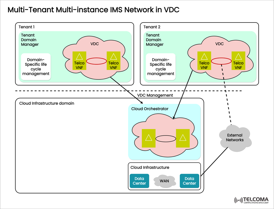
The diagram uploaded illustrates this architecture in detail, demonstrating how Telco VNFs, Virtual Data Centers (VDCs), Tenant Domain Managers, and a Cloud Orchestrator collaborate to provide telecom-grade virtualization on a large scale.
Breaking Down Multi-Tenant Multi-Instance IMS
Let’s clarify some terms:
Multi-Tenant: Different independent tenants (like various operators or companies) utilize the same cloud infrastructure.
Multi-Instance: Each tenant has their own instance of IMS (IP Multimedia Subsystem), ensuring full logical and operational separation.
In this architecture, each tenant’s IMS operations — such as Call Session Control Functions (CSCFs), Home Subscriber Servers (HSS), and Application Servers — are executed as Telco Virtual Network Functions (VNFs) within a Virtual Data Center (VDC).
This model guarantees dedicated network performance and configuration autonomy for each tenant while keeping the infrastructure shared and centrally managed.
Overview of the Architecture
The diagram shows a layered architecture split into two main domains:
Tenant Domain (one for each tenant)
Cloud Infrastructure Domain (common to all tenants)
Let’s dive into each domain.
A. Tenant Domain
Each tenant — marked as Tenant 1 and Tenant 2 in the diagram — signifies an independent operator or organization using the shared telecom cloud.
Key Components:
Tenant Domain Manager: * Controls the tenant’s VDC and Telco VNFs. * Manages domain-specific lifecycle tasks, like deploying, scaling, and recovering IMS VNFs. * Ensures compliance with policies, version handling, and service configuration consistency.
Virtual Data Center (VDC): * A logical segment of the shared cloud just for one tenant. * Houses various Telco VNFs, like CSCFs, HSS, and other IMS elements. * Provides isolation for network, compute, and storage, ensuring tenant independence.
Telco VNFs: * The foundational components of IMS services — set up as virtual machines or containers within the VDC. * Include various IMS elements and supportive service functions (e.g., SBCs, MGCFs, and AS).
Domain-Specific Lifecycle Management: * Each tenant can carry out full lifecycle operations — provisioning, configuration, scaling, recovery, and termination — for their own VNFs. * This offers autonomy and flexibility for each tenant without needing central orchestration for routine tasks.
In short, each tenant’s VDC acts like a mini cloud — self-managed but securely governed within the shared setup.
B. Cloud Infrastructure Domain
This is the base layer that supports and links all tenant VDCs.
- Cloud Orchestrator
The central management component in charge of setting up and coordinating tenant environments.
Oversees VDC creation, lifecycle management, and orchestration among tenants.
Communicates with tenant domain managers through VDC management APIs.
Guarantees fair resource allocation and policy enforcement among tenants.
Works with the NFV Orchestrator (NFVO) and VIM (Virtualized Infrastructure Manager) for resource deployment at the infrastructure level.
Cloud Infrastructure
Made up of several data centers connected via a WAN (Wide Area Network).
Offers compute, storage, and networking resources dynamically to tenant VDCs.
Ensures geographic redundancy, load balancing, and data locality for high availability.
Connectivity to External Networks
The architecture features secure connections to external networks, including: * Public Internet * Other operator networks * Enterprise VPNs
These links allow IMS instances to cater to real-world users and to integrate with other network domains.
Understanding How Multi-Instance IMS Operates in a Multi-Tenant VDC Setup
The system operates through a layered orchestration approach, incorporating both tenant-specific and infrastructure-wide management.
Step 1: VDC Provisioning
When a new tenant comes aboard, the Cloud Orchestrator sets up a dedicated VDC for them.
Resource limits, security guidelines, and SLA parameters are specified.
Step 2: VNF Deployment
The Tenant Domain Manager installs Telco VNFs (IMS components) within the VDC.
Each VNF is configured as a complete IMS instance — logically isolated, but functioning on the shared cloud.
Step 3: Lifecycle Operations
Tenants can manage their IMS lifecycle operations like: * Software updates * Elastic scaling * Fault recovery * Performance tracking
Step 4: Cross-Domain Orchestration
The Cloud Orchestrator maintains consistent orchestration across multiple tenants.
It manages the physical and virtual resources underneath, keeps an eye on resource usage, and makes sure SLA agreements are upheld.
Step 5: External Connectivity
VNFs in the VDCs connect to external networks to provide IMS services like VoLTE, VoWiFi, or SIP-based multimedia communication.
Comparison Table: Multi-Instance vs. Shared-Instance IMS
Feature Multi-Instance IMS Shared-Instance IMS
Tenant Isolation Strong (dedicated instance) Weak (shared processes)
Resource Efficiency Moderate High
Customization High per tenant Limited
Fault Containment Fully isolated Shared risk
Scalability Independent Centralized
Use Case MVNOs, Enterprises, 5G slices Small operators, testbeds
Integration with NFV and Cloud Orchestration Frameworks
The multi-tenant multi-instance IMS model works seamlessly with ETSI NFV architecture and cloud-native orchestration platforms.
NFVO (Network Functions Virtualization Orchestrator): Manages end-to-end VNF service chaining and resource oversight.
VIM (Virtual Infrastructure Manager): Handles the virtualized resources like compute, storage, and networking.
Cloud Orchestrator: Connects NFVO with tenant domains, allowing automated VDC setups and VNF instantiation.
This integration guarantees a policy-driven, automated, and standardized deployment across the telecom cloud landscape.
The Role of Automation and AI in VDC Management
Future setups enhance this architecture with AI-driven orchestration and closed-loop automation:
Predictive scaling based on traffic patterns.
AI-assisted fault prediction and recovery.
SLA-aware resource scheduling.
Smart network slicing orchestration.
These advancements make the multi-tenant IMS cloud architecture self-optimizing and capable of adapting to changing network demands.
Conclusion
The Multi-Tenant Multi-Instance IMS Network in VDC marks a new era in telecom cloud development — blending virtualization, automation, and orchestration into a cohesive model.
By allowing each tenant to run their own IMS instance within a separate VDC, operators strike the right balance between autonomy, scalability, and efficiency.
Supported by centralized orchestration and automated lifecycle management, this model equips telecom networks to cater to a variety of service providers, MVNOs, and enterprises — all built on a common, cloud-native foundation.
With the growth of 5G, edge computing, and network slicing, this architecture will be crucial in delivering agile, scalable, and multi-domain IMS services throughout the global telecom network.