
Non-Roaming 5G System Architecture: Reference Point Representation Explained
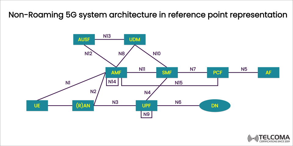

Non-Roaming 5G System Architecture in Reference Point Representation
The 5G Core Network (5GC) takes a fresh approach with something called reference point representation. This is all about how different network functions (NFs) interact. While the 5G Service-Based Architecture (SBA) emphasizes service-oriented communication through APIs, reference point representation zooms in on the logical interfaces (N1–N15) that link these network functions.
Understanding these references is super important for grasping how signaling and data move throughout the 5G Core, especially in non-roaming scenarios where a subscriber is served directly by their home network.
Why Reference Point Representation Matters
These reference points help by providing clarity on:
Logical Connectivity: It shows which network functions are connected and why.
Signaling Paths: It illustrates how control-plane and user-plane messages travel.
Deployment Understanding: This aids telecom engineers in planning integrations and troubleshooting networks.
This kind of representation is often found in 3GPP TS 23.501 specifications, which help standardize the way equipment vendors connect their components.
Key Components of the Non-Roaming 5G System
Take a look at the diagram showing the key network functions (NFs) in the 5G Core (5GC). Here’s a quick overview of what each one does:
Network Function (NF) | Description
UE (User Equipment) | The device (like your smartphone or IoT sensor) that accesses the 5G network.
(R)AN (Radio Access Network) | This provides the wireless interface (NR or LTE) and connects UE to the core network over N2/N3.
AMF (Access and Mobility Management Function) | Manages registration, coordinates authentication and mobility, plus connection context.
SMF (Session Management Function) | Takes care of PDU sessions, IP address allocation, and picks User Plane Functions (UPF).
UPF (User Plane Function) | Directs user data traffic between UE and external data networks (DN).
UDM (Unified Data Management) | Holds subscription data and provides authentication credentials along with policy info.
AUSF (Authentication Server Function) | Handles primary subscriber authentication.
PCF (Policy Control Function) | Issues policy rules regarding QoS, access control, and session management.
AF (Application Function) | Works with the PCF to influence policy choices based on application needs.
DN (Data Network) | External networks like the public internet, private enterprise networks, or cloud services.
Reference Points (N1–N15) and Their Purpose
The true power of this representation lies in how it clearly defines reference points. Each one (N1, N2, N3, etc.) establishes a communication path.
Reference Point | Connects | Function
N1 | UE ↔ AMF | NAS signaling between device and core network.
N2 | (R)AN ↔ AMF | Control-plane signaling between access network and AMF.
N3 | (R)AN ↔ UPF | User-plane interface carrying the actual data traffic.
N4 | SMF ↔ UPF | Control interface for UPF session management and forwarding rules.
N5 | AF ↔ PCF | Application influence on policy decisions.
N6 | UPF ↔ DN | Data path to external data networks (internet or enterprise).
N7 | SMF ↔ PCF | Policy control signaling for session management.
N8 | AMF ↔ UDM | Access to subscription data and retrieval of authentication info.
N9 | UPF ↔ UPF | User-plane interconnection (when multiple UPFs are linked).
N10 | SMF ↔ UDM | Session data and policy authorization.
N11 | AMF ↔ SMF | Session management control signaling.
N12 | AMF ↔ AUSF | Authentication signaling.
N13 | AUSF ↔ UDM | Transfer of subscriber authentication data.
N14 | AMF ↔ AMF | Inter-AMF communication (like during handovers or mobility events).
N15 | SMF ↔ PCF (optional direct interface) | Policy updates for session QoS.
Understanding the Control Plane and User Plane Separation
A fundamental concept in 5G architecture is the CUPS model (Control and User Plane Separation).
Control Plane (CP): This manages signaling (AMF, SMF, PCF, AUSF, UDM).
User Plane (UP): This is responsible for data forwarding (UPF).
Separating these two enhances flexibility and scalability. Plus, it lets UPF be set up closer to users (think edge computing), which cuts down on latency and opens the door for low-latency services like AR/VR, self-driving cars, and industrial automation.
Step-by-Step Example: PDU Session Establishment
Let’s break down a simplified call flow using these reference points:
UE Registration (N1, N2, N8, N12, N13):
UE sends a registration request (N1) to the AMF.
AMF checks with AUSF (N12) for authentication, pulling subscriber data from the UDM (N13).
AMF gets the subscriber profile (N8) from UDM.
Session Setup (N11, N10, N7, N4):
AMF tells SMF (N11) to set up a PDU session.
SMF engages with UDM (N10) for session data and with PCF (N7) for policy rules.
SMF chooses UPF and configures forwarding rules through N4.
User Plane Activation (N3, N6):
(R)AN creates N3 tunnel with UPF.
UPF starts routing user traffic to DN via N6.
This entire process happens smoothly, ensuring connectivity and QoS tailored to what the subscriber needs.
Advantages of the Reference Point Model
Clarity in Design: Helps engineers map out signaling and data flows accurately.
Standardization: Makes sure equipment works together across different vendors and meets 3GPP standards.
Troubleshooting Aid: Eases fault isolation by tracing back through reference points.
Supports Roaming & Interworking: Offers a foundational model that can expand into roaming situations with additional interfaces.
Challenges in Real-World Deployment
Even with a set reference point model, operators run into a few challenges:
Interface Complexity: Lots of reference points mean more effort in configuration and integration.
Security Considerations: Each interface needs to be secured (using IPsec, TLS) to keep signaling attacks at bay.
Interoperability Testing: Working in multi-vendor settings demands thorough validation.
Conclusion
The Non-Roaming 5G System Architecture in Reference Point Representation offers a vital perspective on how 5G core network functions communicate with one another. It highlights the logical interfaces (N1–N15) that make smooth connectivity possible.
For telecom engineers and network architects, getting a grip on this reference point model is essential for effective network planning, deployment, and troubleshooting. It complements the service-based architecture (SBA) model, giving a detailed, interface-level view that helps ensure robust, interoperable, and future-ready 5G networks.