
PDCCH Control Region in 4G LTE vs CORESET in 5G NR: A Complete Technical Comparison

PDCCH Control Region in 4G LTE vs CORESET in 5G New Radio
Switching from 4G LTE to 5G New Radio (NR) has really transformed how we think about flexibility and spectral efficiency, especially when it comes to the design of control channels. A big change is how the PDCCH (Physical Downlink Control Channel) is set up and sent out.
In LTE, the PDCCH stayed in a fixed Control Region, but with 5G NR, it has moved to a Configurable Control Resource Set (CORESET). This shift allows for more dynamic allocation of control channels within Bandwidth Parts (BWPs).
This article dives into how this transition happened, what the new structure looks like, and the benefits that come with it, with an image comparing the control channel designs of LTE and NR.
Understanding the Basics: What is PDCCH?
The Physical Downlink Control Channel (PDCCH) plays a key role in both LTE and NR systems, carrying crucial control information like:
Scheduling grants for downlink and uplink
Hybrid ARQ (HARQ) feedback
Resource allocation details
Modulation and Coding Scheme (MCS)
Power control commands
Without PDCCH, UEs (User Equipments) wouldn’t be able to decode data channels (PDSCH/PUSCH), so it’s basically the “control nerve center” for any cellular frame.
4G LTE PDCCH Control Region: Fixed and Uniform
In 4G LTE, the PDCCH is fixed in place at the start of each subframe.
Key Characteristics of LTE PDCCH:
Location: Positioned right at the beginning of the LTE subframe.
Span: Covers 1 to 3 OFDM symbols (occasionally 4 for specific use cases).
Bandwidth: Extends across the entire system bandwidth.
Resource Mapping: Utilizes Control Channel Elements (CCEs) spread out across the bandwidth using interleaving.
Limitation: All UEs must keep an eye on the full bandwidth, even if they’re only using a slice of it for data.
Implications:
This fixed setup does make things simpler, but it comes with drawbacks in terms of flexibility and power efficiency:
Wastes resources for UEs on the periphery or those needing only a narrow allocation.
Raises decoding complexity since all UEs have to monitor the entire bandwidth.
Makes spectrum usage less fluid.
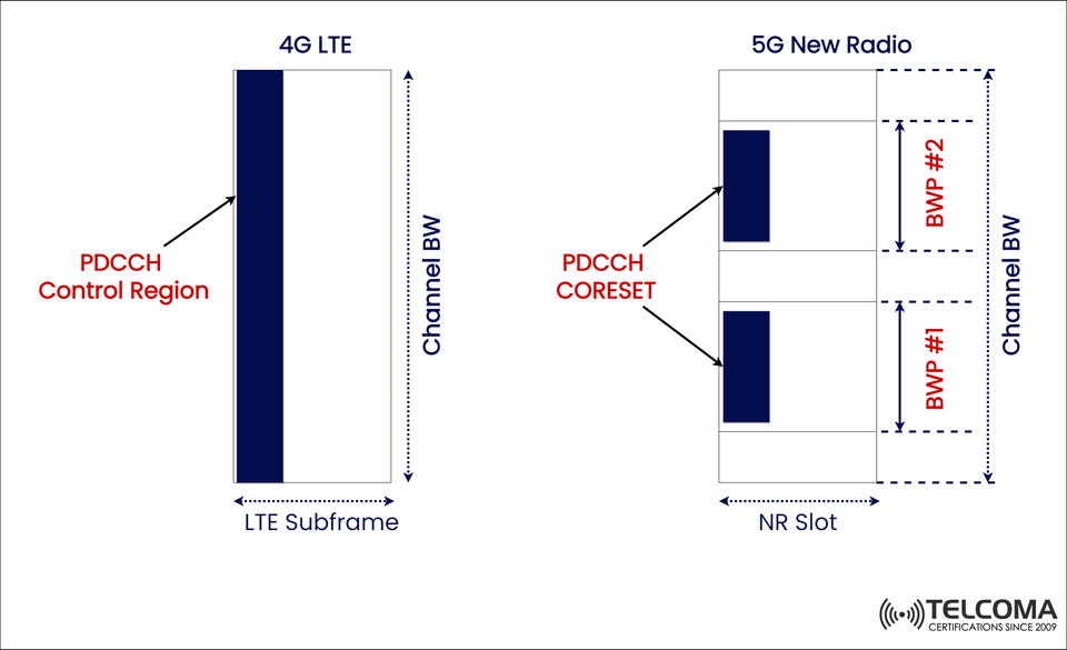
You can see this clearly on the left side of the image, where a single vertical control region (dark blue) spans the channel’s bandwidth — a clear sign of LTE’s rigid approach.
5G NR PDCCH CORESET: Flexible and Configurable
With 5G NR, the traditional PDCCH Control Region was swapped out for the CORESET (Control Resource Set). This is a configurable resource block that dictates where and how control channels are transmitted.
The right side of the image shows how CORESETs can be flexibly positioned within the NR slot and can exist in various Bandwidth Parts (BWPs).
Key Characteristics of 5G CORESET:
Location: Can be located anywhere within the NR slot and its bandwidth.
Size: Defined in terms of Resource Blocks (RBs) and OFDM symbols.
Bandwidth Flexibility: Not limited to the full system bandwidth; can be narrowed down to smaller regions.
Mapping: Similar to LTE's approach but employs Resource Element Groups (REGs) put into Control Channel Elements (CCEs) in a more flexible way.
Customization: Each UE can receive its own CORESET and related Search Space.
Thanks to this design, 5G NR makes massive scalability possible, accommodating everything from low-power IoT devices to high-throughput mobile broadband needs.
Bandwidth Parts (BWP): The Key to CORESET Efficiency
One of the standout features in 5G NR is the introduction of Bandwidth Parts (BWPs), which are essentially subsets of the overall channel bandwidth.
As illustrated in the image:
The complete Channel Bandwidth is divided into several BWPs (like BWP #1 and BWP #2).
Each BWP can have its own CORESET setup.
UEs are only required to track control info within their active BWP — saving energy and processing power.
Advantages of BWP-Based CORESETs:
Energy Efficiency: UEs don't have to decode across the whole bandwidth.
Interference Management: Control channels can be placed away from data-heavy areas.
Custom Scheduling: Different UEs can utilize unique CORESETs tailored to their specific services.
For instance, an IoT device in BWP #1 might work with a tighter CORESET, while a high-throughput user in BWP #2 could have access to a broader control region — all within the same NR slot.
Technical Comparison Table: LTE vs. NR Control Regions
Feature4G LTE PDCCH Control Region5G NR PDCCH CORESET Location Fixed at start of subframe Anywhere within slot Band width Usage Full system bandwidth Limited to CORESET region Symbol Duration1–3 OFDM symbols Configurable (1–3 OFDM symbols)Flexibility Rigid and uniform Highly flexible Energy Efficiency Low (UE monitors all BW)High (UE monitors active BWP only)Scheduling Adaptability Limited Dynamic per UE Supported Scenarios Uniform broad band Diverse use cases (eMBB, URLLC, mMTC)
How CORESET Improves Network Performance
- Enhanced Spectral Efficiency
By tightening the control region to smaller bandwidths, NR reduces overhead while freeing up more resources for user data.
- Better Interference Management
Operators can strategically place CORESETs in lower-interference areas, which makes decoding more reliable for users on the cell edge.
- Dynamic Scheduling and Multi-Service Support
5G NR networks can tailor CORESETs for various services — for instance:
Low-latency CORESETs for URLLC (Ultra-Reliable Low-Latency Communications).
Wider CORESETs for eMBB (Enhanced Mobile Broadband).
- Improved Power Consumption
Since UEs only need to keep track of their assigned CORESET and BWP, energy use — especially for IoT and low-power gadgets — drops significantly.
CORESET and Search Space Relationship
In 5G NR, Search Space determines where a UE looks for its control info within a CORESET.
Each UE is assigned one or more Search Spaces.
Search Spaces correspond to a specific CORESET.
This flexibility allows different UEs to decode their PDCCHs at varying times and frequencies, boosting reliability and efficiency.
This design is quite different from LTE, where all UEs looked for control messages in the same area at the same time.
Why This Evolution Matters
The shift from a static PDCCH control region to a dynamic CORESET architecture isn’t just a protocol tweak — it reflects a change in design philosophy.
In LTE:
Simplicity was the priority.
Every UE shared the same control setup.
Efficiency worked alright for uniform traffic.
In 5G NR:
There’s a demand for service diversity (like IoT, VR, V2X, etc.) and flexibility.
Networks adapt control regions based on individual user needs and services.
Operators gain more control over how spectrum is utilized.
This makes CORESET crucial for realizing the three pillars of 5G — eMBB, URLLC, and mMTC.
Conclusion
The PDCCH Control Region in LTE and the CORESET in 5G NR highlight how mobile communication standards are evolving toward greater flexibility and efficiency.
In LTE, the fixed PDCCH region simplified things but lacked adaptability. In contrast, the CORESET framework in 5G NR enables customizable control areas that align with Bandwidth Parts, Search Spaces, and the dynamic needs of users — leading to smarter, more energy-efficient, and scalable control signaling.
As 5G networks roll out worldwide, grasping how CORESET interacts with BWPs is key for telecom engineers and researchers working to enhance next-gen radio systems.