
TFM with Single Communication Link: Understanding Time-Frequency Mapping in OFDM Systems

TFM with a Single Communication Link: A Closer Look at OFDM Resource Allocation
In the fast-changing world of wireless communication, making good use of the spectrum is super important. Whether we’re talking about 4G LTE, Wi-Fi 6, or the cutting-edge 5G NR (New Radio), each system needs to make the best use of its time and frequency resources to ensure fast and reliable connections.
One of the big players in this optimization game is Time-Frequency Mapping (TFM). The diagram that’s uploaded—“TFM with Single Communication Link”—shows how TFM functions when just one communication link is using the resources in an OFDM (Orthogonal Frequency Division Multiplexing) framework.
In this blog post, we’ll unpack how TFM organizes data transmission, break down the parts of the diagram, and see how it helps achieve efficient and interference-free communication.
Getting to Know Time-Frequency Mapping (TFM)
Time-Frequency Mapping (TFM) outlines how a communication link utilizes certain time and frequency slots during the transmission process. In OFDM systems, data is split into various subcarriers (frequency components) and sent over time slots to ensure strong communication even when there are multiple paths involved.
TFM plays a crucial role in allocating these resources accurately—managing when and where the data is sent.
Breaking Down the Diagram: TFM with a Single Communication Link
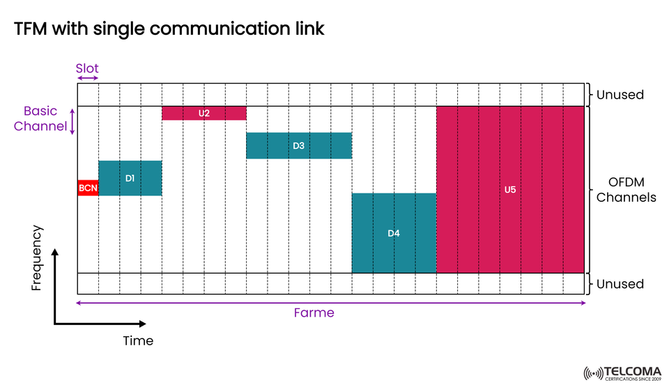
The diagram illustrates a single communication link (one transmitter-receiver pair) functioning over a Time-Frequency grid. It depicts how uplink (U) and downlink (D) transmissions occur at different slots and frequencies throughout an OFDM frame.
Key Elements:
Time (horizontal axis): Represents the flow of transmission over slots within a frame.
Frequency (vertical axis): Showcases the series of OFDM subcarriers categorized into channels.
Basic Channel: The core frequency block assigned to the link.
OFDM Channels: The active subchannels utilized for actual data transmission.
Unused Areas: Portions of frequency or time that are left empty to avoid interference or save power.
Explaining the Blocks:
BCN (Beacon): The little red block at the beginning stands for a beacon or control channel. It’s essential for synchronization and signaling, ensuring that the receiver and transmitter are in sync before data starts flowing.
D1, D3, D4 (Downlink): These blue blocks are where the base station sends data to the user device during the downlink phase. Each downlink takes up specific frequency bands during certain time slots—demonstrating non-contiguous resource allocation to optimize the spectrum.
U2, U5 (Uplink): The magenta blocks represent uplink transmissions, where the user device sends data back to the base station. U5, which takes up a lot of the frame, shows a high-data-rate uplink phase.
Step-by-Step Look at the Transmission Process
Let’s go through the diagram step by step:
Beacon Transmission (BCN): The network kicks things off by sending a BCN signal on the basic channel, offering timing, frequency references, and system info to the user.
Downlink Phase 1 (D1): Once everything’s synchronized, the base station transmits the first downlink data (like control info or setup packets).
Uplink Phase (U2): The user replies by sending back acknowledgments or initial data during the U2 slot.
Downlink Continuation (D3, D4): The network carries on by sending more data chunks in spaced intervals, using the OFDM subcarriers effectively without messing with other systems.
Final Uplink Transmission (U5): The user sends larger data amounts (like sensor data or video packets) over an extended duration, represented by the big U5 block.
This flow illustrates a full communication cycle within a single link, all managed through time-frequency scheduling.
How TFM Optimizes a Single Link
While the diagram shows just one communication link, the principles of TFM make sure that the time-frequency grid is used as effectively as possible.
- Effective Spectrum Use
Rather than hogging a broad bandwidth constantly, the transmitter utilizes non-contiguous subcarriers and intermittent time slots. This helps cut down on unused spectrum and allows for coexisting with other systems.
- Better Interference Management
By spacing out uplink and downlink blocks in both time and frequency, interference between transmissions is lessened—this is crucial for half-duplex systems.
- Adaptable Scheduling
TFM allows for flexible resource scheduling based on the state of the channel, user needs, and latency requirements.
- Energy Efficiency
Because the device only transmits during its assigned slots, it can enter low-power states in between transmissions—an important feature for IoT and battery-operated devices.
Key Technical Terms
Term - Description
Slot: The smallest time unit for resource assignment (like 0.5 ms or 1 ms).
Frame: A complete cycle that includes multiple slots.
Subcarrier: A narrow frequency band utilized in OFDM.
Downlink (D): Transmission from the base station to the user.
Uplink (U): Transmission from the user to the base station.
Beacon (BCN): A synchronization signal to align communication timing.
Unused Band: Frequencies set aside to prevent adjacent channel interference.
TFM with Single vs. Multiple Communication Links
Aspect - Single Communication Link - Multiple Communication Links
Number of Users: One transmitter-receiver pair - Several users at once.
Resource Allocation: Dedicated resources for one link - Shared, dynamic allocation.
Interference Management: Easier (single path) - Complex coordination needed.
Use Case: Point-to-point systems, IoT - Cellular and multi-user 5G.
Efficiency: Moderate - High (thanks to parallel usage).
While a single-link setup is more straightforward, multi-link TFM (as seen in the accompanying diagram) offers much greater overall efficiency for larger deployments.
Real-World Applications
TFM with a single communication link is commonly utilized in:
Wi-Fi and WLAN systems for timed transmissions.
IoT gateways that manage periodic, low-latency data transfers.
Satellite and backhaul links where one user channel spans vast bandwidths.
Testing and validation setups in telecom R&D settings to model channel performance.
These applications really leverage TFM’s organized approach to spectrum management and reducing interference.
Wrapping Up
The idea of TFM with a single communication link might seem straightforward, but it's crucial for effective spectrum management in today’s wireless systems. By smartly dividing time and frequency resources, TFM helps make sure communication between transmitter and receiver happens smoothly with minimal interference and maximum efficiency.
As we move into the era of 5G and 6G, where making efficient use of the spectrum is so important, getting a good grasp on these foundational mechanisms is key. Whether it’s for IoT devices, private networks, or crucial communications, TFM offers the structured flexibility that modern networks rely on.