
Transmitter RF Spectrum Explained: Operating Band, Out-of-Band Emissions, and Spurious Domain

Wireless communication systems, whether it's LTE, 5G, or the upcoming 6G, heavily rely on radio frequency (RF) transmitters to provide reliable signals. But it's important to note that transmitters don't just emit energy within their designated frequency band. They also create unwanted emissions outside the intended range, which can lead to interference and lower the efficiency of the spectrum.
This is where the concept of transmitter RF spectrum comes into play. Organizations like 3GPP, ITU, and ETSI set specific standards for transmitter emissions, breaking them down into three categories:
Understanding the Transmitter RF Spectrum
The RF spectrum of a transmitter can be segmented into three main parts:
- Operating Band
This is the central part of the spectrum where the transmitted signal is found.
It corresponds with the assigned channel bandwidth (like 20 MHz in LTE or up to 400 MHz in 5G NR).
It's crucial that emissions here meet strict spectral mask limits to minimize interference with nearby channels.
The emissions in the operating band are expected and permissible since they represent the actual data being transmitted.
- Out-of-Band Emissions (OoB)
These emissions are found just outside the channel bandwidth, but still relatively close to it.
They occur due to unintended spectral leakage caused by filter limitations, modulation techniques, and non-linearities in the power amplifier.
Standards define this as ΔfOoB (the frequency offset from the channel edge).
Key points:
OoB emissions tend to decrease as you move further away from the operating band.
They can be managed using techniques such as:
Sharp filtering
Digital predistortion (DPD)
Enhanced modulation shaping
If these emissions aren't well-regulated, they can lead to interference with adjacent channel users, which in turn reduces the efficiency of the spectrum.
- Spurious Emissions (Spurious Domain)
These emissions occur far from the operating band, outside the OoB area.
They include emissions resulting from:
Harmonics of the carrier frequency
Intermodulation products
Local oscillator leakage
Standards categorize these into the spurious domain.
For instance:
If a transmitter operates at 2 GHz, it might have spurious emissions at 4 GHz (the second harmonic).
Typically, spurious emission levels are much lower than OoB emissions, but they still need to be controlled.
Controlling spurious emissions is essential to ensure that different services can coexist without causing issues (like interference with satellite, Wi-Fi, or aviation systems).
The Importance of Controlling Transmitter Emissions
- Spectrum Efficiency
In a world where spectrum is a limited resource, reducing unwanted emissions allows for denser frequency reuse and greater capacity.
- Compliance with Regulations
Organizations such as FCC, ETSI, and 3GPP impose strict regulations on OoB and spurious emissions.
Failing to comply can result in penalties, certification issues, or service interruptions.
- Reducing Interference
Unwanted emissions can disrupt adjacent bands, resulting in:
Dropped calls
Slower data speeds
Interference with critical services (like aviation or defense)
- Requirements for 5G and Beyond
5G pushes the boundaries with wideband channels (up to 400 MHz) and massive MIMO arrays, which makes managing emissions even trickier.
Technical Standards for RF Spectrum Emissions
Various regulatory and standard organizations dictate emission limits. Some key players are:
Standard Body Governs Focus Area Example Standard3GPPMobile networks (LTE, 5G)Adjacent channel leakage, OoB3GPP TS 38.104ITU-RGlobal spectrum coordination Harmonics, spurious emissions ITU-R SM.329ETSIEuropean region Emission masks, spurious domain ETSI EN 301 908FCCU.S. regulations Licensed spectrum compliance FCC Part 24/27
These standards lay out power spectral density (PSD) masks and maximum allowed leakage levels to ensure fair use across services.
Techniques for Reducing OoB and Spurious Emissions
Telecom engineers use various hardware and software methods to manage emissions effectively:
Filtering
Bandpass filters ensure a sharp roll-off at channel edges.
Advanced filters are employed in the RF front-ends of smartphones and base stations.
Power Amplifier Linearization
Digital Predistortion (DPD) helps correct for amplifier non-linearities.
It reduces intermodulation distortion that can lead to spurious emissions.
Enhanced Modulation and Coding
Pulse shaping (like Root Raised Cosine filters) smooths out signal edges.
This helps lower OoB emissions in systems that use OFDM.
Antenna Design
Smart antennas and beamforming techniques can help minimize radiated spurious emissions.
Carrier Aggregation Management
Coordinating multiple carriers in 4G/5G can cut down cross-band leakage.
Example: RF Spectrum Requirements in 5G NR
In 5G NR, the transmitter RF spectrum requirements have become stricter:
Channel bandwidths can reach 400 MHz in FR2 (mmWave).
Adjacent Channel Leakage Ratio (ACLR) needs to be greater than 45 dB for several bands.
There are also rigorous spurious emission masks in place to protect nearby satellite and radar services.
This makes spectrum shaping and emission suppression major considerations in the design of 5G radios.
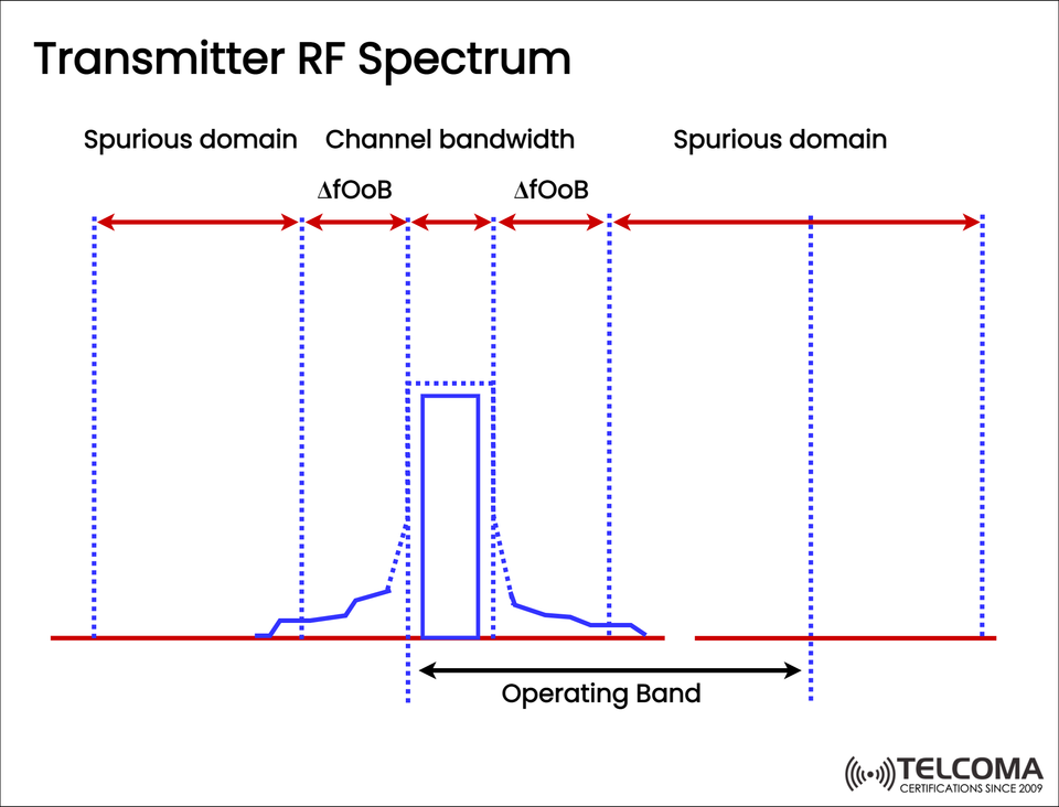
Visual Overview from the Diagram
The uploaded diagram helps illustrate three key areas:
Operating Band: The central zone where the usable signal is found.
OoB Emissions (ΔfOoB): Transition areas just outside the channel.
Spurious Domain: Outer areas positioned far from the band edges.
This clear distinction aids engineers in designing, testing, and certifying transmitters to ensure compliance.
Real-World Challenges in Emission Control
Even with established standards, there are practical hurdles to managing emissions:
Wideband operation: Higher channel bandwidths complicate filtering.
Massive MIMO: The use of multiple antennas raises the chances of intermodulation products.
Device miniaturization: Smaller RF components make it tough to achieve effective filtering.
Energy efficiency must also be considered, as stronger filtering or linearization often leads to higher power consumption.
Finding the right balance between performance, cost, and compliance remains crucial for telecom vendors.
Looking Forward: Emission Control in 6G
As we look to the future, 6G systems will present new challenges:
Expect even wider bandwidths (potentially at GHz levels).
Operations at THz frequencies where managing non-linearities becomes even tougher.
There will be a push towards AI-driven spectrum monitoring to spot and reduce spurious emissions in real time.
Smarter reconfigurable intelligent surfaces (RIS) could help direct and minimize unwanted emissions.
Ultimately, effective emission control will be vital for ensuring spectrum coexistence and promoting green networking.
Key Takeaways
The transmitter RF spectrum encompasses the operating band, OoB emissions, and spurious domain.
OoB emissions occur near the band edges, while spurious emissions can be found much further away from the operating band.
Standards (3GPP, ITU, FCC, ETSI) set strict limits on emissions to ensure interference-free coexistence.
Techniques like filtering, DPD, and pulse shaping play a key role in reducing emissions.
When it comes to 5G and beyond, managing emissions gets more complex due to factors like wider bandwidths, massive MIMO, and mm Wave/THz operations.
Conclusion
The transmitter RF spectrum is not just about the useful signal; it also includes unwanted out-of-band and spurious emissions that need careful regulation. For telecom professionals, understanding these categories is essential for designing, optimizing, and certifying wireless systems.
As we transition from 5G to 6G, emission standards will likely become stricter, with solutions increasingly relying on AI-driven optimization, smarter filtering, and advanced RF design. In the end, managing transmitter emissions is crucial for ensuring efficient spectrum use, adhering to regulations, and providing high-quality wireless communication for billions of users around the globe.