
TSDSI RIT Logical Layer Architecture Explained for 5G Networks

The Telecommunications Standards Development Society, India (TSDSI) has put together the Radio Interface Technology (RIT) for 5G to contribute to global standardization efforts under the ITU IMT-2020 framework.
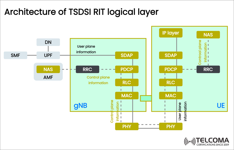
At the core of this setup is the logical layer architecture, which outlines how user plane and control plane data move between the User Equipment (UE), the gNB (next-generation NodeB), and the 5G Core Network (5GC).
The diagram included shows the TSDSI RIT logical layer architecture, highlighting important protocol layers like SDAP, PDCP, RLC, MAC, PHY, RRC, and NAS.
This article breaks down the architecture to make it easier for telecom engineers, researchers, and enthusiasts to understand how the TSDSI RIT guarantees reliable, secure, and efficient communication.
Key Components in the TSDSI RIT Logical Layer
The architecture can be split into three key areas:
User Equipment (UE): This refers to the mobile device or terminal.
gNB (Next-Generation NodeB): The base station that oversees radio resources and protocol layers.
5G Core Network (5GC): Comprised of AMF, SMF, UPF, and DN, it handles authentication, mobility, session, and data management.
Each component is vital for transmitting both control plane information (like signaling and management) and user plane information (the actual data traffic).
Control Plane vs. User Plane
To really get a handle on the architecture, it helps to distinguish between the two types of communication:
User Plane: This handles real user data such as internet browsing, video streaming, or calls.
Control Plane: Manages signaling info, including mobility, session setup, and QoS policies.
In the TSDSI RIT logical layer:
User plane information travels through SDAP → PDCP → RLC → MAC → PHY.
Control plane information moves through NAS, RRC, PDCP, RLC, MAC, PHY.
Protocol Layers in the TSDSI RIT Logical Architecture
Let’s break down what each protocol layer in the diagram does.
- Non-Access Stratum (NAS)
Found in both UE and AMF (Access and Mobility Management Function).
Handles signaling that’s not reliant on radio access tech (things like authentication, registration, session management).
Sits above RRC and is sent via control plane channels.
- Radio Resource Control (RRC)
Resides in both UE and gNB.
Manages control plane signaling between UE and gNB.
Key responsibilities include:
Connection establishment/release.
Mobility management (handover).
QoS and security configuration.
- Service Data Adaptation Protocol (SDAP)
User plane only, located in UE and gNB.
Maps QoS Flows to Data Radio Bearers (DRBs).
Guarantees QoS differentiation for different applications (like video calls vs. browsing).
- Packet Data Convergence Protocol (PDCP)
Present in both control and user planes.
Functions include:
Header compression (ROHC).
Security: ciphering and integrity protection.
Packet duplication for URLLC.
- Radio Link Control (RLC)
Makes sure packets are delivered reliably and handles segmentation/reassembly.
Has different modes:
Acknowledged Mode (AM).
Unacknowledged Mode (UM).
Transparent Mode (TM).
- Medium Access Control (MAC)
Responsible for multiplexing and scheduling data flows.
Implements HARQ (Hybrid Automatic Repeat Request) for error correction.
Works closely with the gNB scheduler for resource distribution.
- Physical Layer (PHY)
Deals with modulation, coding, and the transmission process over the air.
This is the final stage before signals are sent out via antennas.
Logical Flow in TSDSI RIT
User Plane Flow
UE IP Layer: Data packets are created.
SDAP: Maps those packets to QoS flows.
PDCP: Compresses headers and encrypts the data.
RLC: Segments data for sending.
MAC: Multiplexes the data and applies HARQ.
PHY: Sends transport blocks over the air to gNB.
Control Plane Flow
NAS (UE): Creates signaling messages.
RRC (UE): Passes on signaling to gNB.
PDCP → RLC → MAC → PHY: Processes the signaling down the stack.
NAS (AMF): Control messages end in the 5G Core.
Simplified Example
Picture a user streaming a 4K video:
User plane: The video data flows from UE → gNB → UPF → DN, moving through the SDAP, PDCP, RLC, MAC, and PHY layers.
Control plane: At the same time, RRC signaling guarantees that resources are allocated, handovers happen seamlessly, and QoS is upheld.
This parallel processing makes for a smooth service experience.
Comparison Table of Functions
Layer Plane Location Key Functions NAS Control UE, AMF Registration, session management RRC Control UE, gNB Mobility, QoS, connection control SDAP User UE, gNB QoS mapping, bearer management PDCP Both UE, gNB Security, header compression, duplication RLC Both UE, gNB Segmentation, retransmission MAC Both UE, gNB Multiplexing, HARQ, scheduling PHY Both UE, gNB Transmission over air interface
Why TSDSI RIT Matters
The TSDSI RIT logical architecture is important for several reasons:
Regional Significance: Tailored to address India’s specific connectivity needs (like rural broadband).
Compatibility: Works well with global 5G standards.
Efficiency: Enhances spectrum usage and network performance.
Versatility: Accommodates various use cases — eMBB, URLLC, and mMTC.
Practical Applications of the TSDSI RIT Logical Layer
This architecture isn't just theoretical; it really serves as the backbone for practical 5G rollouts. Let’s dive into how the logical layer affects real-life situations:
- Enhanced Mobile Broadband (eMBB)
Services like high-speed video streaming, AR/VR experiences, and cloud gaming depend on smart handling of SDAP and PDCP.
By duplicating PDCP, we can boost reliability for ultra-HD streaming.
- Ultra-Reliable Low-Latency Communication (URLLC)
For things like industrial automation, remote surgeries, and self-driving cars, we need super-low latency.
The RLC and MAC layers are crucial here because they cut down on retransmissions and allow for quick fixes using HARQ.
- Massive Machine-Type Communication (mMTC)
IoT devices in smart cities or agriculture produce a ton of small data packets.
The logical structure makes sure there’s efficient QoS differentiation, prioritizing important IoT signals (like alarms) over less critical data.
The TSDSI RIT in the Indian Context
While the global 3GPP 5G NR framework shaped its design, the TSDSI RIT comes with features tailored to India’s requirements:
Low-Mobility Large Cell (LMLC): This helps achieve broader coverage in rural and semi-urban regions.
Efficient Spectrum Usage: So important in markets where mid-band and mmWave spectrum is limited.
Support for Various Devices: Catering to everything from affordable IoT sensors to high-end smartphones.
Conclusion
The TSDSI RIT logical layer architecture lays out a framework for managing both control plane signaling and user plane traffic in 5G networks. By clarifying the role of each protocol layer — from NAS and RRC in the control plane to SDAP, PDCP, RLC, MAC, and PHY in the user plane — this architecture promotes secure, efficient, and QoS-focused communication.
For telecom professionals, grasping this layered setup is key for implementing, optimizing, and troubleshooting next-generation 5G networks.
Not only does the TSDSI RIT align with global IMT-2020 standards, but it also fosters regional innovation, marking it as a vital component of India’s 5G journey.