
Understanding 5G Functional Split: CU-DU Mapping in High, Low, and Cascade Split Architectures

Introduction: Breaking Down the 5G RAN
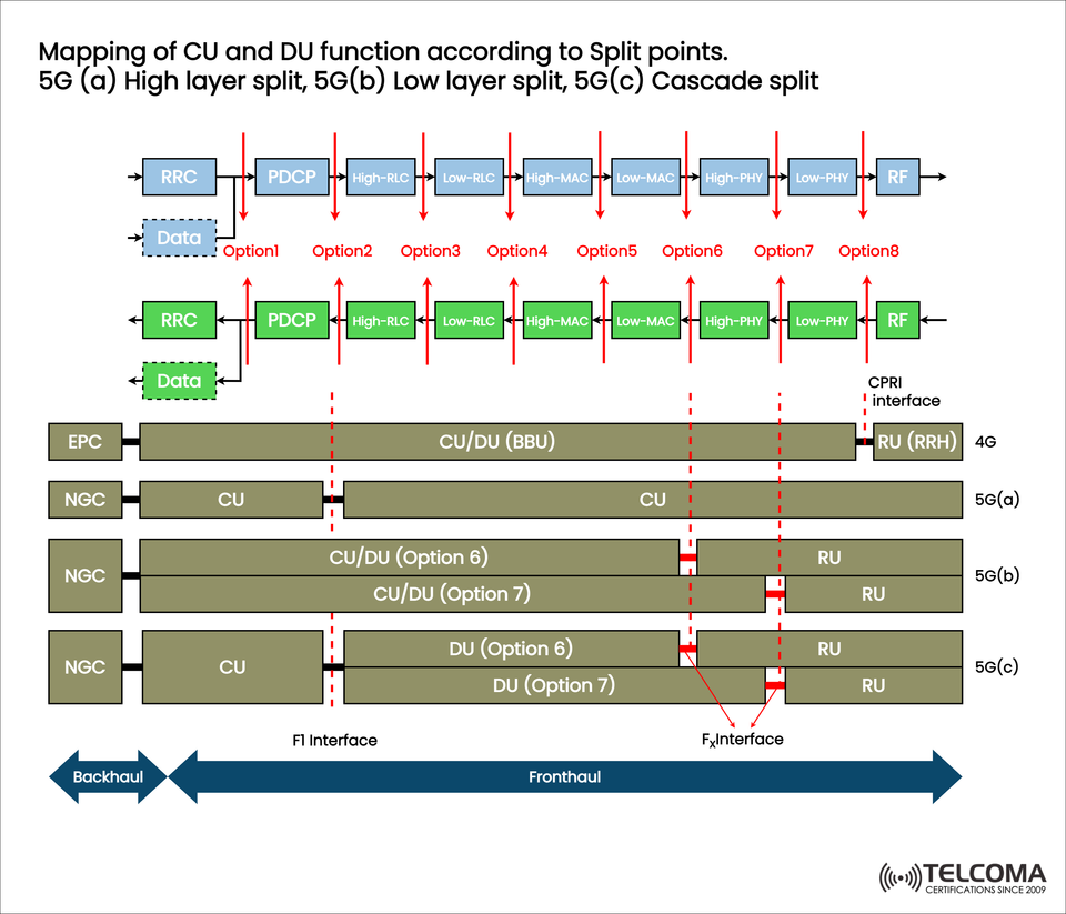
The 5G Radio Access Network (RAN) marks a significant shift in flexibility and scalability by introducing functional splits among the Central Unit (CU), Distributed Unit (DU), and Radio Unit (RU).
In the old 4G LTE setup, the Baseband Unit (BBU) and the Remote Radio Head (RRH) worked together through a CPRI (Common Public Radio Interface) link. With 5G, that approach is disaggregated, paving the way for virtualization, cloud-native deployment, and the ability to mix vendors.
The attached image illustrates this progression, highlighting how various split options (Option 1 to Option 8) define the functional roles of the CU, DU, and RU. These lead to what we call High-Layer Split, Low-Layer Split, and Cascade Split.
What Are 5G Functional Split Options?
Functional splits define where in the protocol stack the line is drawn between centralized and distributed processing.
Each split option relates to a specific division of RAN functions, which can include:
RRC (Radio Resource Control)
PDCP (Packet Data Convergence Protocol)
RLC (Radio Link Control)
MAC (Medium Access Control)
PHY (Physical Layer)
The 3GPP outlines several split points (Options 1–8), each offering unique trade-offs around latency, fronthaul capacity, and processing complexity.
Transitioning from 4G to 5G Split Architecture
In 4G LTE, the Baseband Unit (BBU) consolidated all the digital baseband functions and connected to the Remote Radio Head (RRH) using the CPRI interface.
From the image, you can see that:
4G relied on a tight coupling between the BBU and RRH.
5G introduces a logical separation into CU, DU, and RU, all linked via the F1 and Fx interfaces.
This new separation offers much more flexibility, allowing for cloud-based RAN (C-RAN), Open RAN, and distributed setups that are tailored to various performance demands.
The Three Main Types of 5G Functional Splits
5G(a) – High Layer Split (HLS)
The High-Layer Split (Option 2) divides the RRC and PDCP layers (found in the CU) from the RLC, MAC, and PHY layers (located in the DU).
Architecture Overview:
CU: Manages RRC and PDCP functions.
DU: Handles the RLC, MAC, and PHY layers.
Interface: The F1 interface (with F1-C for control and F1-U for user).
Defined by:
📘 3GPP TS 38.401
Advantages:
Lowers fronthaul bandwidth needs compared to low-layer splits.
Simplifies virtualization — CU can be in centralized data centers.
Eases multi-vendor compatibility.
Challenges:
There's a need to keep latency in check (ideally under 10 ms).
DU hardware has to be close enough to the RU for time-sensitive PHY functions.
Use Cases:
Cloud RAN (C-RAN) setups.
Urban and suburban networks with available fiber.
Multi-vendor RAN scenarios.
5G(b) – Low Layer Split (LLS)
The Low-Layer Split delves deeper into the PHY and MAC layers. Standard options include Option 6 (between MAC and PHY) and Option 7.x (within the PHY layer).
Architecture Overview:
CU/DU combined take care of upper RAN layers (RRC, PDCP, RLC).
RU (Radio Unit) manages some of the PHY processing.
Interface: Typically referred to as the Fx interface (linking DU and RU).
Option 6 (MAC/PHY Split):
CU/DU handle up to the MAC layer.
RU manages PHY and RF functions.
Moderate latency requirement (~250 µs).
Option 7.x (Intra-PHY Split):
Further splits within PHY (like precoding, FFT/IFFT).
Stricter latency requirement (<100 µs).
Allows for some centralization of PHY processing.
Advantages:
Enables better coordination between cells.
Supports advanced techniques like CoMP (Coordinated Multipoint).
Fits scenarios needing massive MIMO and beamforming.
Challenges:
Requires high-bandwidth, low-latency fronthaul (often fiber or mmWave links).
Needs complex synchronization between DU and RU.
Use Cases:
Dense urban areas needing real-time coordination.
Private 5G or industrial setups where ultra-low latency is essential.
5G(c) – Cascade Split (Hybrid or Cascaded Split)
The Cascade Split merges both high-layer and low-layer splits, leading to a three-tier structure: CU, DU, and RU.
Architecture Overview:
CU: Handles RRC and PDCP (high-layer control and data processing).
DU: Manages RLC, MAC, and some PHY components.
RU: Takes care of low-PHY and RF functions.
Interfaces: * F1 Interface (CU to DU) * Fx Interface (DU to RU)
Advantages:
Balances centralization with low-latency processing.
Allows for dynamic functional placement according to network needs.
Supports network slicing and flexible resource management.
Challenges:
Coordination between layers can become complex.
Advanced orchestration and synchronization are necessary.
Multi-hop latency can impact real-time applications.
Use Cases:
Edge Cloud or distributed edge setups.
Operators moving from traditional RAN to fully virtualized Open RAN.
Comparison Table: Functional Split Types
Split Type Split Option(s) CU Functions DU Functions RU Functions Latency Sensitivity Bandwidth Requirement
High-Layer Split (5G(a)) Option 2 RRC, PDCP RLC, MAC, PHY RF Medium (<10 ms) Low to Medium**
Low-Layer Split (5G(b)) Option 6 / 7.x RRC, PDCP, RLC, MAC High-PHY Low-PHY, RF High (<1 ms) High**
Cascade Split (5G(c)) Combination RRC, PDCP RLC, MAC, High-PHY Low-PHY, RF High (<1 ms) High
Understanding Interfaces: Backhaul, Midhaul, and Fronthaul
The image also highlights the transport segments' evolution in 5G:
Backhaul: Links the CU to the 5G Core (NGC).
Midhaul (F1 Interface): Connects CU ↔ DU.
Fronthaul (Fx Interface): Links DU ↔ RU.
Key Differences:
Segment Connects Typical Protocols Latency Target
Backhaul CU ↔ Core IP, SCTP, GTP 10–50 ms
Midhaul CU ↔ DU F1-AP, GTP-U <10 ms
Fronthaul DU ↔ RU eCPRI, RoE <1 ms
This layered transport design keeps time-sensitive functions closer to the edge (DU/RU), while management and control can be centralized.
Benefits of Functional Splitting
Using functional splits in 5G brings a bunch of operational and economic perks:
Flexible Deployment: Choose splits based on how dense the network is and what latency you need.
Virtualization Ready: CU and DU can operate as VNFs (Virtual Network Functions).
Multi-Vendor Compatibility: Standardized interfaces (F1, Fx) make it easy to mix and match vendors.
Scalable and Cost-Efficient: Centralized processing cuts down on energy and maintenance costs.
Optimized Performance: Different splits can cater to a wide range of 5G applications—from eMBB to URLLC to mMTC.
Challenges in Adopting Functional Splits
Even with their benefits, rolling out these splits comes with some technical hurdles:
Latency and Synchronization: PHY-level splits need precise synchronization.
Fronthaul Bandwidth: A lot of data throughput is required, especially for low-layer splits.
Interoperability Testing: Ensuring seamless integration across vendors for CU-DU-RU.
Complex Orchestration: Dynamically managing distributed network functions can get tricky.
These challenges are getting tackled through O-RAN Alliance specifications and edge computing frameworks.
Conclusion
The way we map CU and DU functions according to 5G split points is pivotal for shaping modern RAN architecture.
High-Layer Splits (Option 2) lean towards centralized, cloud-based setups.
Low-Layer Splits (Option 6/7.x) facilitate low-latency, high-performance edge deployments.
Cascade Splits fuse both types for ultimate adaptability and optimization.
By choosing the right split based on latency, bandwidth, and deployment needs, operators can craft 5G networks that are resilient, efficient, and ready for the future.