
Understanding 5G NAS Signaling and Control Plane Interactions in the 5G Core Network

5G NAS Signaling and Control Plane Interactions Unpacked
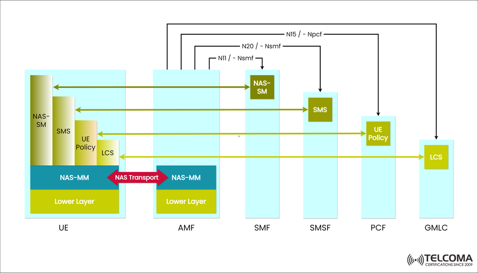
The Non-Access Stratum (NAS) is a key part of the 5G System (5GS) setup, outlining how User Equipment (UE) interacts with the 5G Core Network (5GC) without getting into the radio access layer. The image uploaded nicely illustrates how NAS-MM (Mobility Management) supports NAS transport for important services like Session Management (SM), Short Message Service (SMS), User Equipment Policy Control, and Location Services (LCS).
In this piece, we’ll dive into the 5G NAS signaling structure, look at the roles of each core network function (AMF, SMF, SMSF, PCF, and GMLC), and explain how NAS helps streamline control plane communication in the 5G landscape.
What is NAS Signaling in 5G?
NAS (Non-Access Stratum) operates above the Access Stratum (AS) layer, focusing on control plane signaling between the UE and the Access and Mobility Management Function (AMF).
NAS messages are used for:
Registration and authentication
Mobility management
Session creation and handling
Service requests and policy control
SMS and location-based services
Unlike AS signaling, which deals with radio procedures, NAS takes care of core network control and end-to-end signaling to ensure 5G service continuity.
Overview of the 5G NAS Architecture
The image shows how NAS operates through various interfaces and functional entities:
Entity Function Key Interface UE (User Equipment)Initiates NAS signaling; starts registration and service requests. Connects to AMF through NAS Transport AMF (Access and Mobility Management Function)Ends NAS signaling; manages authentication, mobility, and routing. Interfaces with SMF, SMSF, PCF, and GMLCSMF (Session Management Function)Oversees PDU sessions, allocates IP addresses, and manages QoS.N11/NsmfSMSF (SMS Function)Handles SMS over NAS services.N20/NsmfPCF (Policy Control Function)Oversees UE policy, QoS, and charging rules.N15/NpcfGMLC (Gateway Mobile Location Center)Manages location services (LCS).LCS Interface
This architecture guarantees smooth transport of NAS messages between UE and core functions through the NAS-MM (Mobility Management) layer inside the AMF.
Components of NAS in the 5G Control Plane
The figure outlines various components interacting under NAS transport:
a. NAS-MM (Mobility Management)
NAS-MM deals with:
UE registration and deregistration
Security context management
Managing mobility events (like handovers or idle mode)
Routing NAS messages between UE and AMF
In the diagram, the NAS-MM section in the UE and AMF is linked by a NAS Transport arrow, representing the encapsulated signaling communicated over the N2 interface.
b. NAS-SM (Session Management)
NAS-SM is responsible for establishing, adjusting, and terminating PDU sessions that connect to the data network.
The NAS-SM signaling flows between UE and SMF through AMF.
The AMF acts as a relay, ensuring secure NAS transport.
Interfaces:
N11/Nsmf connects AMF and SMF for session management procedures.
This guarantees that session management requests—like IP allocation or QoS changes—are handled securely and effectively.
c. SMS (Short Message Service)
The 5G system keeps supporting traditional SMS, routed through the SMS Function (SMSF) using NAS signaling.
SMS messages from the UE go through NAS Transport to AMF, followed by SMSF.
The N20/Nsmf interface connects AMF with SMSF.
This NAS-based SMS process ensures messaging stays available even when data sessions are down.
d. UE Policy
Policy Control in 5G ensures services comply with set Quality of Service (QoS) rules and charging policies.
The UE Policy function in AMF communicates with the Policy Control Function (PCF) through the N15/Npcf interface.
Policy decisions control session priorities, bandwidth, and user-specific configurations.
This setup allows operators to provide distinct service experiences based on user profiles and network conditions.
e. LCS (Location Services)
The Location Services (LCS) feature is supported through the Gateway Mobile Location Center (GMLC), allowing location tracking for UE.
LCS messages are exchanged via NAS transport between UE, AMF, and GMLC.
These services are crucial for emergency calls, asset tracking, and 5G IoT applications that need pinpoint accuracy.
The LCS section in the diagram shows how location data requests securely flow through NAS signaling.
How NAS Transport Works
NAS Transport is the method that carries NAS messages between the UE and the AMF over the N1 interface.
The NAS Transport process includes:
Encapsulation – NAS messages from the UE are packed into a secure NAS container.
Transmission through Access Stratum – The message passes through the radio interface to reach AMF.
Decryption and Routing – AMF authenticates and sends NAS messages to the appropriate network functions like SMF or PCF.
This method guarantees end-to-end encryption, reliability, and a clean split between access and core signaling.
Interfaces and Signaling Paths in the Diagram
The figure shows several key reference points:
InterfaceBetweenFunctionN1UE ↔ AMFNAS message transportN11 / Nsmf AMF ↔ SMF Session ManagementN20 / Nsmf AMF ↔ SMSFSMS signalingN15 / Npcf AMF ↔ PCF Policy control LCS Interface AMF ↔ GMLC Location Services
Each interface has a unique role in directing NAS messages to the right network entities to handle authentication, session setup, policy enforcement, and location inquiries.
Advantages of NAS-Based Control Signaling in 5G
NAS signaling offers a range of technical and operational benefits in 5G networks:
Separation of control and user planes enhances flexibility.
Secure communication thanks to NAS encryption and integrity protection.
Efficient signaling flow minimizes latency and signaling load.
Multi-service support (SMS, policy, and location) via a unified NAS transport.
Scalability that accommodates millions of IoT and mobile devices at once.
This approach allows operators to provide advanced services like network slicing, real-time analytics, and low-latency IoT applications.
NAS Signaling Flow Example
Here’s a quick look at a simplified signaling flow:
UE kicks off registration by sending NAS-MM messages to AMF.
AMF authenticates the UE and sets up a security context.
NAS-SM messages are exchanged through AMF to the SMF for session setup.
The PCF provides policy decisions that guide the SMF.
SMS and LCS services are handled via SMSF and GMLC respectively, all using NAS transport methods.
This coordinated effort ensures a secure, efficient, and service-focused control plane.
Conclusion
The 5G NAS signaling architecture underpins control plane communication in 5G networks. As the image shows, NAS-MM serves as the main transport mechanism linking UE with various core functions like SMF, SMSF, PCF, and GMLC.
With clearly defined interfaces such as N11, N15, N20, and LCS, 5G enables sophisticated services while keeping high security and flexibility.
For telecom engineers and professionals, getting a grasp on NAS signaling is essential to navigate the operational complexities of the 5G Core (5GC) — the foundational layer for the next wave of connected services.