
Understanding 5G NR Carrier Bandwidth Part (BWP): Concept, Configuration, and Benefits

Carrier Bandwidth Part (BWP) in 5G NR: A Thorough Technical Summary
Carrier Bandwidth Part (BWP) is one of the new features that was introduced with 5G New Radio (NR). While LTE used fixed carrier bandwidth, 5G NR allows the carrier bandwidth to be divided into smaller bandwidth parts, which optimizes performance, energy efficiency, and spectrum utilization.
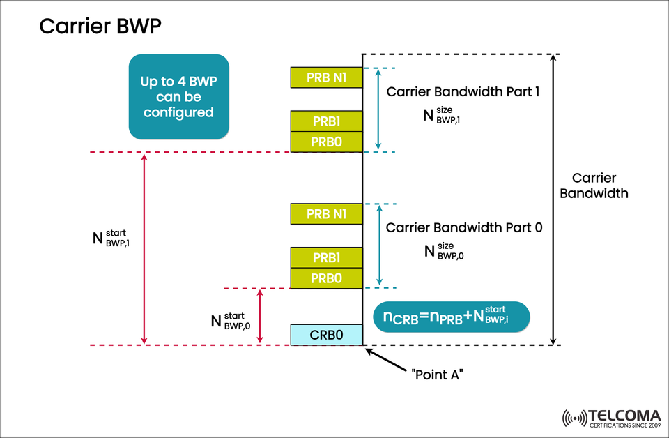
The image "Carrier BWP" represents how the total carrier bandwidth can be divided into bandwidth parts (BWPs), each starting from its own defined point and defined size based on Physical Resource Blocks (PRBs).
What is a Bandwidth Part (BWP)?
A Bandwidth Part (BWP) is a portion of the total channel bandwidth where the User Equipment (UE) is allowed to transmit and receive data.
In 5G NR, the UE is not required to monitor the entire carrier bandwidth, which could be up to 100 MHz in FR1 and up to 400 MHz in FR2. Rather, the 5G NR system can configure the UE to operate within a BWP that best meets the needs or capabilities of the UE.
The incorporation of the BWP helps to balance power consumption, flexibility and system performance.
Grasping the Image: Carrier BWP Structure
The image gives a visual illustration of how BWPs fit into the total carrier bandwidth:
The right part of the image represents the total Carrier Bandwidth, which is comprised of Carrier Bandwidth Part 0 and Carrier Bandwidth Part 1.
Each BWP can be identified by
Starting position (Nᵗˢᵗᵃʳᵗ_BWP,i)
Size (Nˢⁱᶻᵉ_BWP,i)
These two sets of values represent the set of PRBs that the UE will use in the carrier.
The notation n_CRB = n_PRB + Nᵗˢᵗᵃʳᵗ_BWP,i also indicates, how the index of the Common Resource Block (CRB), is related to the index of the Physical Resource Block (PRB) in the BWP.
The "Point A" at the lower part of the image represents the point of reference (CRB0) and the assignment and indexing starts from that point.
The note, "Up to 4 BWP can be configured" represents the 3GPP standard of up to 4 configured BWPs in each direction (UL/DL).
Why 5G Introduced Bandwidth Parts
5G NR flexibility across frequency ranges (FR1 and FR2)m necessitates future-proof scalable bandwidth management. However, forcing a UE to continuously monitor a large bandwidth -
Increase power consumption if the device uses a battery,
Increase complexity in RF/bwithbase processing.
Bandwidth Parts address this dilemma by allowing:
- Full utilization of the carrier by the network.
- Reduced monitoring area by UE.
- Switch back and forth between wide and narrow bandwidth depending on the type of traffic.
This behavior allows high-end devices to utilize the entire bandwidth when needed (a large size download) while low power devices can operate in smaller BWPs so that they do not need to waste power.
Key Parameters Defining a BWP
Each BWP is identified by the following parameters:
Parameter Description
Nᵗˢᵗᵃʳᵗ_BWP,i Starting position of the BWP in CRB units
Nˢⁱᶻᵉ_BWP,i Size (number of RBs) of the BWP
Point A Reference point for the carrier (start of CRB0)
n_CRB = n_PRB + Nᵗˢᵗᵃʳᵗ_BWP,i A formula used to map PRBs to CRBs
Active BWP The BWP currently being used for transmission/reception
Configured BWPs Up to 4 per direction (UL/DL)
These parameters ensure that the devices are correctly aligned and receive efficient scheduling from the network irrespective of the amount of devices connected to a single carrier.
Carrier Bandwidth and Bandwidth Part
It is important to distinguish between Carrier Bandwidth and BWP.
Aspects Cowasition Carrier Bandwidth Bandwidth Part (BWP)
Definition Total bandwidth of the NR carrier Subset of carrier bandwidth used by UE
Usage Entire spectrum available to gNB Partial bandwidth allocated to UE
Flexibility Fixed per carrier.
BWP Types
5G NR identifies the following BWP configurations for operational flexibility:
Initial BWP:
Available for the duration of the initial access and random access procedure.
Provides a configured state before RRC is established.
Configured BWP:
Configured via RRC signaling.
Can be enabled or disabled dynamically.
Active BWP:
The BWP in use for the communication.
May change mid-operation based on DCI signaling.
This enables an adaptive operation where the network can switch between configurations based on service requirements, conditions on the channel, and capabilities of the device.
The steps are as follows:
Configuring the BWP:
The gNB uses RRC signaling to configure multiple BWPs for the UE.
Activating the BWP:
Initially, one BWP will be active.
BWP Switching:
If a traffic type changes, the gNB can initiate the active BWP to switch, via DCI (Downlink Control Information) commands.
For example:
For small data packets, activate a narrow BWP (e.g. 20 PRBs);
Using a demanding throughput switch to a wide BWP,
(e.g., 100 PRBs).
This allows for seamless optimization between power efficiency and data performance.
Advantages of Bandwidth Parts in 5G NR
- Power Efficiency
Since the UE observes and processes across the BWP that is active, not across the entire carrier bandwidth, it enables less RF and baseband power consumption.
- Spectrum Flexibility
Operators can efficiently manage spectrum for multiple applications.
Operated for both eMBB (wideband) and IoT (narrowband) services on a single carrier.
- Multi-Service Capability
Enables the co-existence of devices having different bandwidth capabilities.
This is well-suited for mixed traffic scenarios, such as smart cities or industrial IoT environments.
- Dynamic Adaptation
BWPs can be dynamically switched based on network load, mobility, and QoS requirements.
- Reduced Complexity in User Equipment/Devices
Devices with limited capabilities may still operate using narrower BWPs, all without needing to fully operate as a carrier.
Final Thoughts
The Carrier Bandwidth Part (BWP) is a fundamental feature of 5G NR’s flexible and scalable radio interface. It allows the network to dynamically slice larger carriers into a number of smaller, more manageable pieces-of spectrum. This maximizes spectrum utilization and reduces power consumption of device operating time, limits signaling overheads while allowing for multi-service coexistence.
As shown in the image, a carrier can be configured with up to four BWPs. Each BWP is defined by a start point and size, which is mapped from “Point A”, the carrier reference point.
Fundamentally, BWPs make 5G much more agile, with respect to meeting the demands of low-power IoT sensors or carrying gigabit-level throughput to smartphones. BWPs are the ultimate statement of efficiency, flexibility, and scalability — all principles of the 5G NR standard.