
Understanding 5G NR Minimum and Maximum Channel Bandwidth: Numerology, SCS, and Resource Blocks Explained

5G NR Minimum and Maximum Channel Bandwidth: A Practical Guide
In 5G New Radio (NR), channel bandwidth is essential for determining the data rate, latency, and spectral efficiency of a network. Unlike LTE, which had a fixed subcarrier spacing of 15 kHz, 5G brings in scalable numerologies. This flexibility allows for variable subcarrier spacing and dynamic bandwidth allocation across a range of frequencies.
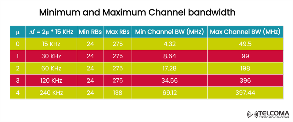
The accompanying image gives a clear overview of how the minimum and maximum channel bandwidths are set for each numerology (μ), illustrating how subcarrier spacing (Δf) influences the number of resource blocks (RBs) and the total channel bandwidth in MHz.
In this piece, we’ll unpack what this table means, look at the connections between numerology, resource blocks, and bandwidth, and discuss how these setups affect the design of 5G networks.
The Basics of 5G Numerology (μ) and Subcarrier Spacing (Δf)
In 5G NR, numerology (μ) defines the subcarrier spacing (Δf), which is the frequency difference between adjacent subcarriers in an OFDM signal. The system uses a scalable formula for subcarrier spacing:
Δf=15 kHz×2μ
Numerology (μ) | Subcarrier Spacing (Δf) | Typical Use Case
0 | 15 kHz | FR1 (sub-6 GHz) for wide coverage
1 | 30 kHz | FR1 (mid-band, e.g., 3.5 GHz)
2 | 60 kHz | FR1/FR2 edge (e.g., 6 GHz)
3 | 120 kHz | FR2 (mmWave)
4 | 240 kHz | FR2 (Ultra-high mmWave)
Every time μ increases, the subcarrier spacing doubles, which halves the symbol duration. This adaptability allows 5G NR to cater to various frequency bands and deployment scenarios, from wide-area coverage in lower bands to ultra-high throughput in mmWave.
Important Parameters in the Table
The image outlines several key parameters that define the minimum and maximum channel bandwidths in 5G NR:
μ (Numerology Index): This determines subcarrier spacing (Δf)
Δf (kHz): Subcarrier spacing = 15 × 2^μ
Min RBs / Max RBs: Minimum and maximum number of resource blocks
Min Channel BW (MHz): Bandwidth occupied by minimum RBs
Max Channel BW (MHz): Bandwidth occupied by maximum RBs
Each resource block (RB) consists of 12 subcarriers, and the total channel bandwidth depends on how many RBs you've configured for a certain subcarrier spacing.
Breaking Down the 5G NR Channel Bandwidth Table
μΔf = 2^μ × 15 kHz Min RBs Max RBs Min Channel BW (MHz)Max Channel BW (MHz)015 kHz2427554.3249.5130 kHz2427558.699.2260 kHz2427517.21983120 kHz2427534.53964240 kHz2413869.1397.44
How to Calculate These Values
The occupied bandwidth (BW) of an OFDM signal can be estimated using:
BW=12×N_{RB}×Δf
Here’s how it breaks down:
12 is the number of subcarriers per resource block
N_{RB} is the number of resource blocks
Δf is the subcarrier spacing in Hz
Let’s look at an example from the table:
Example:
For μ = 1 (30 kHz SCS) and Max RBs = 275:
BW=12×275×30 kHz=99 MHz
This aligns with the Max Channel BW in the image, confirming the formula's validity.
Minimum vs. Maximum Channel Bandwidth
Minimum Channel Bandwidth
This represents the smallest bandwidth setup that still accommodates 24 RBs within the spectrum.
It's used in narrowband 5G channels or situations where spectrum availability is tight.
Offers better coverage due to the narrower subcarriers.
Maximum Channel Bandwidth
This defines the largest bandwidth configuration the system can manage for a specific numerology.
Useful in high-capacity deployments to achieve peak data rates.
Higher bandwidths minimize symbol duration, allowing for low latency but needing higher SNR and clear line-of-sight (LoS) conditions.
- Observations from the Table
- Bandwidth Doubles with Each Numerology Step
Each increase in μ (which doubles Δf) roughly doubles both minimum and maximum bandwidths.
For example, you go from 49.5 MHz (μ=0) to 99 MHz (μ=1) to 198 MHz (μ=2).
Consistent RB Range (24 to 275)
The number of RBs stays mostly constant for μ = 0 to 3.
For μ = 4 (240 kHz), however, the max RBs drop to 138 since larger subcarrier spacing limits the number that can fit in the spectrum.
Ultra-High Frequencies
Numerologies 3 and 4 relate to FR2 (mmWave) operations.
They enable extreme throughput over short distances, making them perfect for fixed wireless or hotspot setups.
Practical Insights for 5G Design
A. FR1 (Sub-6 GHz)
Uses μ = 0, 1, or 2.
Maximum bandwidth per carrier is 100 MHz.
Strikes a balance between coverage and capacity.
For instance, the C-band (3.5 GHz) typically adopts μ=1 (30 kHz SCS).
B. FR2 (mmWave)
Uses μ = 3 or 4.
Can support bandwidths of 400 MHz or more.
Facilitates multi-gigabit speeds with ultra-low latency.
The 28 GHz and 39 GHz 5G bands usually work with μ=3 or 4.
- Understanding Resource Blocks (RBs)
Each resource block (RB) is made up of:
12 subcarriers (frequency domain)
1 slot (time domain, based on numerology)
The total bandwidth occupied by N_{RB} resource blocks is:
BW_{RB}=12×N_{RB}×Δf
So, if you increase the subcarrier spacing (Δf), you get more bandwidth but fewer RBs can fit into the available spectrum.
Bandwidth vs. Latency Trade-Off
One of the perks of having flexible numerology is the ability to juggle the trade-off between coverage, capacity, and latency:
Numerology (μ) | SCS (kHz) | Symbol Duration (µs) | Latency Impact | Coverage
0 | 15 | 66.67 | Higher | Wide
1 | 30 | 33.33 | Medium | Moderate
2 | 60 | 16.67 | Low | Reduced
3 | 120 | 8.33 | Very Low | Limited
4 | 240 | 4.17 | Ultra Low | Very Limited
Lower numerologies (μ=0,1) tend to support coverage and stability.
Meanwhile, higher numerologies (μ=3,4) allow for ultra-low latency and high throughput.
Real-World Example: C-Band 5G NR
Let’s take a look at a C-band 5G carrier (3.5 GHz) with:
Numerology (μ) = 1 (30 kHz SCS)
Channel bandwidth = 100 MHz
From the table, Max RBs = 275 corresponds perfectly to 99 MHz, highlighting how C-band 5G is standardized for 100 MHz carriers.
This setup can deliver:
Peak speeds over 1 Gbps,
A reasonable cell radius for urban deployments,
Effective spectrum utilization with 3GPP-compliant gear.
Why Minimum and Maximum Channel Bandwidth is Important
Spectrum Licensing: Aids operators in planning their deployments within licensed frequency ranges.
Carrier Aggregation (CA): Helps determine how many component carriers can be combined to hit gigabit speeds.
UE Capability: User devices need to support specific bandwidth classes (like up to 100 MHz for FR1 or 400 MHz for FR2).
Network Optimization: Engineers can fine-tune numerology and bandwidth to hit latency, coverage, and throughput goals.
Summary Table: Key Insights
Numerology (μ) | Subcarrier Spacing (kHz) | Typical Band | Max Bandwidth (MHz) | Deployment Type
0 | 15 | FR1 (low-band) | 50 | Wide coverage
1 | 30 | FR1 (mid-band) | 100 | Urban macro
2 | 60 | FR1/FR2 edge | 200 | High-capacity cells
3 | 120 | FR2 (mmWave) | 400 | Ultra-capacity zones
4 | 240 | FR2 (mmWave) | 400 | Extreme speed mmWave
Conclusion
The configuration of Minimum and Maximum Channel Bandwidth is crucial to understanding how 5G NR adjusts to various spectrum environments. Each numerology strikes a balance between coverage, latency, and capacity, making 5G both versatile and future-ready.
Lower numerologies (μ=0,1) enable broad coverage and stable connectivity.
Higher numerologies (μ=3,4) power ultra-fast, low-latency mmWave networks.
By mastering these setups, telecom experts can design 5G networks that optimize both spectral efficiency and user satisfaction, fully realizing the potential of next-gen wireless technology.