
Understanding 5G RRC Reconfiguration and Data Transfer in Standalone Networks

5G RRC Reconfiguration and Data Transfer: The Last Step in 5G Standalone Registration
In a 5G Standalone (SA) network, connecting the User Equipment (UE) to the 5G NodeB (gNB) involves more than just basic signaling. After completing the NAS and AS security procedures, the system moves to RRC Reconfiguration. This is where the UE finalizes its radio setup, establishes PDU sessions, and kicks off actual data transfer.
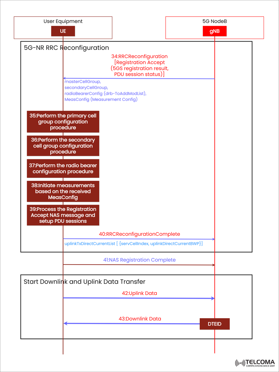
The diagram below shows this crucial phase of the 5G SA registration, highlighting the message flow from RRC Reconfiguration to the start of uplink and downlink data exchange. Let’s break down each step to see how the UE goes from completing registration to being fully ready for data sessions.
Overview: What is RRC Reconfiguration in 5G?
The Radio Resource Control (RRC) Reconfiguration process is key for setting up the UE’s radio interface. It guides the UE on how to:
Set up or change radio bearers
Configure measurement settings
Allocate cell group parameters (Primary and Secondary)
Activate or deactivate carrier aggregation or dual connectivity
Start data transfer capabilities
In simple terms, RRC Reconfiguration serves as a link between connection setup and active communication, finalizing both control plane and user plane resources.
Step 34: RRC Reconfiguration [Registration Accept + PDU Session Status]
Once NAS and AS security are successfully established, the gNB sends the RRC Reconfiguration message to the UE. This message contains the Registration Accept content, which shows that the network has approved the UE’s registration and lays out essential configuration details.
Key Components of the RRC Reconfiguration Message:
master Cell Group – Configuration info for the main serving cell, covering scheduling, uplink power control, and DRX settings.
secondary Cell Group – Info for any secondary cell(s) used in carrier aggregation or dual connectivity.
radio Bearer Config (drb-To Add ModList) – Defines Data Radio Bearers (DRBs) that support the PDU session(s).
Meas Config (Measurement Config) – Outlines measurement rules (like signal quality reports and neighbor cell checks).
This message marks the UE's shift from registration procedures to setting up active service.
Step 35–37: Cell Group and Bearer Configuration Procedures
After the UE gets the RRCReconfiguration message, it undertakes several key configuration tasks to pave the way for data transfer.
Step 35: Perform the Primary Cell Group Configuration
The UE kicks things off by configuring parameters for the Primary Cell Group, which includes:
Scheduling info
HARQ and MAC configurations
Physical uplink control channel (PUCCH) settings
Power control parameters
This step ensures the UE’s primary connection with the gNB is solid and optimized for signaling on both uplink and downlink.
Step 36: Perform the Secondary Cell Group Configuration
If the network offers Carrier Aggregation (CA) or Dual Connectivity (DC), the gNB tells the UE to configure secondary cells. This allows the UE to:
Work with extra frequency carriers
Boost data throughput and connection strength
Setting up the secondary group enhances overall radio performance and capacity for ongoing PDU sessions.
Step 37: Perform the Radio Bearer Configuration Procedure
Next up, the UE configures Data Radio Bearers (DRBs) based on the details received in drb-To Add Mod List. Each DRB matches a PDU Session set up through the NAS layer and handles user-plane data, like internet traffic, voice packets, or application streams.
By this stage, the UE has completed:
NAS-level registration and authentication
AS-level (RRC) security configuration
DRB establishment for PDU sessions
The radio interface is now ready for measurement activation and performance monitoring.
Step 38: Initiate Measurements Based on MeasConfig
With all the bearers and cells set up, the UE starts measurement activities as defined by MeasConfig:
RSRP, RSRQ, and SINR for both serving and neighbor cells
Beam-level measurements for managing beams in 5G NR
Mobility-related metrics for potential handovers
These measurements help the gNB and UE adjust dynamically to changing radio conditions, optimizing performance and ensuring smooth mobility management.
Step 39: Process Registration Accept NAS Message and Setup PDU Sessions
Now, the UE processes the Registration Accept NAS message, which includes:
The final 5GS registration result
PDU session statuses (like active, pending, or rejected)
Configuration data needed for each session
With this message, the UE sets up PDU sessions by linking the NAS-level session info (from the SMF/AMF) with the configured DRBs. Each active session corresponds to a QoS flow, making sure network traffic gets handled according to its service needs (like low latency for voice or high throughput for video).
Step 40: RRC Reconfiguration Complete
Once all configurations are successfully applied, the UE sends an RRC Reconfiguration Complete message back to the gNB. This serves as:
Confirmation that all radio and bearer configurations were completed correctly
A signal that the UE is ready to communicate data
The message includes parameters like:
uplink Tx Direct Current List { serv Cell Index, uplink Direct Current BWP}
These details define the UE’s uplink bandwidth and scheduling structure, boosting data transmission efficiency.
Step 41: NAS Registration Complete
After the RRC layer confirms its setup, the UE sends a NAS Registration Complete to the core network via the gNB. This message wraps up:
The UE’s registration in the 5G system
The activation of the default PDU session
The establishment of UE context at the AMF and SMF
From here on, the UE is regarded as fully registered and authenticated — ready for exchanging user data.
Step 42–43: Start Downlink and Uplink Data Transfer
The last phase signals the shift from signaling to actual data communication.
Step 42: Uplink Data
The UE starts sending uplink data packets to the gNB via the established DRBs. Each packet is identified using the DTEID (Data Tunnel Endpoint Identifier), linking the user’s data session to the right PDU session in the UPF (User Plane Function).
Step 43: Downlink Data
The gNB works with the UPF to send downlink data back to the UE. This data flow is directed based on:
DTEID mapping
QoS Flow Identifiers (QFI)
Session rules from the SMF
At this point, both the uplink and downlink transmissions are active, completing the registration and establishing continuous user-plane connectivity.
Importance of RRC Reconfiguration in 5G SA Networks
RRC Reconfiguration is more than just a setup step — it ensures:
Efficient spectrum use through dynamic carrier assignment
Secure data transmission with AS-level protection
QoS assurance via properly mapped PDU sessions
Mobility readiness from activated measurements
End-to-end data continuity from UE to UPF
This coordination guarantees that both signaling and user data flows work securely and efficiently within the 5G SA structure.
Conclusion
The RRC Reconfiguration and Data Transfer phase is the final milestone in 5G SA registration — the moment when a UE becomes fully operational on the network. From configuring radio bearers and PDU sessions to establishing uplink and downlink data paths, every step is tuned to deliver high-speed, low-latency communication with solid security.
For telecom professionals, getting to grips with these flows offers important insight into how 5G SA enables seamless connectivity — laying the foundation for ultra-reliable, high-throughput services that define the next generation of mobile technology.