
Understanding 5G Standalone Access: The UE Role in Registration and Connection Setup

5G Standalone Access — Understanding the UE Role
The 5G Standalone (SA) architecture marks a significant advancement in mobile communications by enabling ultra-reliable, low-latency connections without depending on older LTE networks. In this fully 5G setup, the User Equipment (UE) talks directly to the gNB (5G NodeB) and the 5G Core (5GC), engaging in complex signaling procedures to create secure, high-speed links.
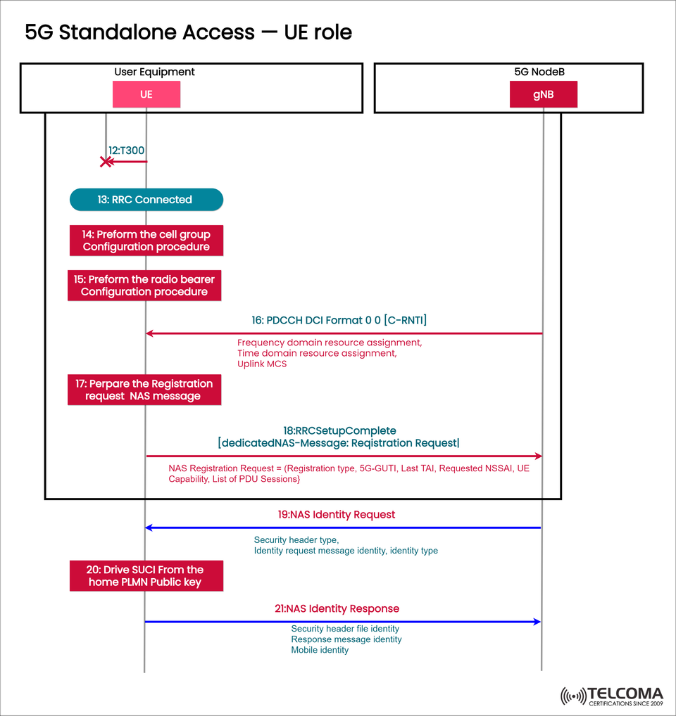
The diagram titled “5G Standalone Access — UE Role” illustrates the series of operations that the UE performs during its registration and configuration process. This guide walks through each step—from establishing the RRC connection to NAS identity procedures—providing telecom professionals with a clear understanding of how the UE behaves in a 5G SA setting.
Overview of UE’s Role in 5G Standalone Access
In a 5G SA network, the UE takes on several responsibilities: initiating access, configuring cells, setting up radio bearers, and handling NAS-level registration.
Here's a brief look at the overall steps involved:
RRC (Radio Resource Control) connection establishment with the gNB.
Configuration of cells and radio bearers.
Preparation and sending of the NAS Registration Request.
Management of NAS Identity Request and Response procedures.
These steps ensure that the UE is authenticated, securely set up, and ready for seamless communication with the 5G Core (5GC) through the gNB.
The 5G SA Access Flow — Step-by-Step Breakdown
Let’s break down each step from the diagram to see how the UE moves from being idle to fully registered and secure.
Step 12: T300 Timer Expiry
The T300 timer sets a waiting period for the response to the RRC connection setup. If this timer runs out, it indicates that the UE hasn’t received a response from the gNB in time.
When the timer expires, the UE either retries the connection setup or selects a different cell, helping to maintain strong network access even in changing radio conditions.
Step 13: RRC Connected
Once the connection setup is successful, the UE reaches the RRC Connected state.
This is a key milestone, as it allows the UE to exchange both control-plane and user-plane data with the gNB. Being in the RRC Connected state lets the UE:
Schedule resources for uplink and downlink.
Conduct mobility measurements and submit reports.
Activate security and exchange NAS messages.
At this point, the gNB fully manages the UE regarding radio resource control.
Step 14: Perform Cell Group Configuration Procedure
Once connected, the UE goes ahead with the cell group configuration process.
This entails setting up essential parameters for:
Master Cell Group (MCG) — the main connection anchor.
Secondary Cell Group (SCG) — extra cells for boosting capacity in dual connectivity scenarios.
This configuration ensures the UE can effectively communicate with the main serving cell and any additional cells when necessary.
Step 15: Perform the Radio Bearer Configuration Procedure
After setting up the cell group, the UE moves on to radio bearer setup, creating logical connections between the UE and the 5G Core via the gNB.
Radio bearers are responsible for carrying both signaling and user data, and they come in two key types:
SRB (Signaling Radio Bearers): Handle RRC and NAS signaling messages.
DRB (Data Radio Bearers): Manage user-plane data packets.
This setup allows the UE to handle both control and data communication seamlessly.
Step 16: PDCCH DCI Format 0_0 [C-RNTI]
After the radio bearer configuration, the gNB sends Downlink Control Information (DCI) on the PDCCH (Physical Downlink Control Channel).
Here, the C-RNTI (Cell Radio Network Temporary Identifier) uniquely identifies the UE within that cell.
The DCI Format 0_0 message includes:
Frequency domain resource assignment to define the subcarriers used.
Time domain resource assignment to lay out scheduling in time slots.
Uplink Modulation and Coding Scheme (MCS) for data rate and robustness.
This step equips the UE with the info needed to transmit uplink data using the resources allocated.
Step 17: Prepare the Registration Request NAS Message
Once the radio resources are assigned, the UE gets ready to send the NAS Registration Request message.
This NAS message includes critical parameters:
Registration type (whether it's initial or periodic).
5G-GUTI (Globally Unique Temporary Identifier) for identifying the UE.
Last TAI (Tracking Area Identity) to show its location.
Requested NSSAI (Network Slice Selection Assistance Information) for slice assignments.
UE capabilities such as supported radio bands and features.
List of PDU Sessions for user data connectivity.
This message indicates the UE's intention to register with the network and kickstart service access.
Step 18: RRC Setup Complete [dedicated NAS-Message: Registration Request]
The UE wraps the NAS Registration Request into the RRC Setup Complete message and sends it to the gNB.
The RRC Setup Complete message confirms that the UE has finished its RRC setup.
The embedded NAS Registration Request is then passed by the gNB to the AMF in the 5G Core for processing.
This is a pivotal transition from the Access Stratum (AS) to the Non-Access Stratum (NAS) layer.
Step 19: NAS Identity Request
The AMF might respond with a NAS Identity Request, which the gNB forwards to the UE.
This request contains:
Security header type to show what security protection is applied.
Identity request message type and identity type to specify which identity the network needs (like SUCI, GUTI, or IMEI).
This step is part of the authentication and identity verification process.
Step 20: Derive SUCI from the Home PLMN Public Key
To protect the subscriber’s permanent identity (SUPI), the UE generates a SUCI (Subscription Concealed Identifier).
The SUCI is created using:
The home PLMN’s public key (from the USIM).
The SUPI (IMSI).
Encryption algorithm parameters as outlined by 3GPP.
This ensures that the UE’s permanent identity isn't sent in clear text over the air, enhancing user privacy.
Step 21: NAS Identity Response
Finally, the UE sends the NAS Identity Response back to the gNB, which then relays it to the AMF.
This message includes:
Security header field and message identity.
Mobile identity (SUCI or GUTI) based on what the network requested.
At this point, the UE’s identity is securely established, allowing the network to move forward with authentication and generating security keys.
Key Insights for Telecom Professionals
Privacy-first design: The SUCI mechanism helps keep IMSI hidden, enhancing user identity protection.
Modular signaling: RRC and NAS layers work independently but coordinate via encapsulated messages.
Dynamic resource allocation: The PDCCH DCI allows for effective scheduling and uplink data transfers.
Network slicing awareness: The UE’s registration includes Requested NSSAI, ensuring correct slice allocation for services like eMBB or URLLC.
This signaling flow highlights how 5G SA networks are focused on both performance and security, aligning with 3GPP Release 15+ specs.
Conclusion
The 5G Standalone Access (SA) process from the UE’s perspective is detailed and ensures secure, efficient, and high-speed connections. From setting up the RRC connection and configuring radio bearers to handling NAS registration and protecting identities, the UE is actively involved at every connection setup stage.
Grasping this process enables telecom engineers and network architects to enhance signaling performance, address registration issues, and build reliable 5G SA implementations.
As the industry progresses toward network slicing, private 5G, and AI-driven optimization, understanding the UE’s role in Standalone Access is crucial for next-gen mobile networks.