
Understanding 5G User Plane Setup: PDU Session Update and UPF Activation in the 5G Core

5G User Plane Setup: A Closer Look at PDU Session Update and UPF Activation
In the 5G Core Network (5GC), the User Plane Function (UPF) is essential for handling data traffic between User Equipment (UE) and various external data networks. Acting as the anchor for user data, the UPF facilitates packet routing, manages quality of service (QoS), and shapes traffic.
The user plane setup process kicks off when the network activates the user plane for a particular PDU Session. This is done through the Session Management Function (SMF), which works together with the Access and Mobility Management Function (AMF) and the gNB (5G NodeB) to assign IP addresses, create tunnels, and start data flow.
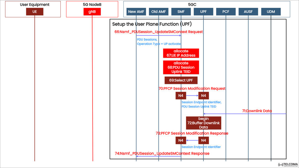
The diagram above showcases this process, illustrating the journey from PDU Session Update to User Plane activation, including the message exchanges among the different entities in the 5G Core.
Key Players in the 5G User Plane Setup
Before we dig into the signaling sequence, it’s important to get familiar with the key entities involved in this process:
Entity | Function in UPF Setup
UE (User Equipment) | The device kicking off the data communication.
gNB (Next-Gen NodeB) | The 5G base station that manages radio access and forwards user plane packets.
AMF (Access and Mobility Management Function) | Oversees mobility, registration, and signaling between UE and the core network.
SMF (Session Management Function) | Takes charge of session setup, changes, and releases; interacts with UPF through the N4 interface.
UPF (User Plane Function) | Responsible for routing user data, enforcing QoS, and managing connections to the Data Network (DN).
Overview of the UPF Setup Process
The User Plane Setup Procedure establishes the route for user traffic between the UE and the data network. Here’s a quick rundown of the main tasks involved:
IP address allocation for the UE.
Assigning Tunnel Endpoint Identifiers (TEIDs) for GTP-U tunnels.
Choosing the best UPF based on policies, network topology, and slices.
Setting up or modifying the PDU session through the SMF.
Sending Packet Forwarding Control Protocol (PFCP) messages for UPF configuration.
This process allows for both uplink (UE → DN) and downlink (DN → UE) data transfers, ensuring efficient session management and quick connectivity.
Step-by-Step Breakdown of the Signaling Flow
Let’s break down the steps depicted in the diagram to clarify how it all works.
Step 66: Nsmf_PDU Session_Update SM Context Request
Entity: New AMF → SMF
Purpose: To activate the User Plane (UP) for the PDU session.
The message indicates operation type = UP activate, directing the SMF to set up the data path.
This kicks off the UPF setup process, including various allocation and configuration tasks on both the SMF and UPF sides.
Step 67: Allocate UE IP Address
The SMF assigns an IP address to the UE for the active PDU session. This address is crucial for routing data and ensuring that user traffic is uniquely identifiable.
The IP might be sourced from the Data Network (DN) or an IP pool managed by the SMF or UPF.
Step 68: Allocate PDU Session Uplink TEID
Next, the SMF designates the PDU Session Uplink TEID (Tunnel Endpoint Identifier). This TEID is utilized on the N3 interface between the gNB and UPF to specify the user plane tunnel.
The uplink TEID is key for correctly mapping user packets between the UE and UPF.
Step 69: Select UPF
Now, the SMF selects the most suitable User Plane Function (UPF) based on:
User’s location and AMF region
Network slice (S-NSSAI)
QoS requirements and service type
Operator policies and network topology
Once the appropriate UPF is chosen, the SMF starts the PFCP (N4 interface) configuration.
Step 70: PFCP Session Modification Request
Entity: SMF → UPF (via N4 interface)
Purpose: To set up or alter the UPF session for the active PDU session.
This message includes:
Session Endpoint Identifier (SEID)
PDU Session Uplink TEID
QoS enforcement rules
Forwarding parameters
The PFCP protocol makes sure that the control (SMF) and user (UPF) planes are synchronized.
Step 71: Downlink Data Received
At this point, the UPF starts receiving downlink data from the external network even before the UE is fully prepared for it.
Since the user plane setup is still in the works, the UPF temporarily buffers these incoming packets to avoid data loss.
This mechanism helps ensure that no user data is lost during the transition or setup phase.
Step 72: Buffer Downlink Data
The UPF begins buffering the downlink data until the session modification wraps up. Once the PFCP session is active, these buffered packets get sent to the UE via the gNB.
This guarantees a lossless data delivery experience, even during session activation.
Step 73: PFCP Session Modification Response
Entity: UPF → SMF (via N4 interface)
Purpose: To confirm that the UPF has been successfully configured.
The UPF acknowledges with the following identifiers:
Session Endpoint Identifier (SEID)
Uplink and Downlink TEIDs
At this stage, the user plane is ready to handle data transfer in both directions.
Step 74: Nsmf_PDU Session_Update SM Context Response
Entity: SMF → New AMF
Purpose: To indicate that the UPF setup and SM context update are complete.
This response confirms that the PDU session is fully active, allowing the UE to start exchanging user data through the 5G Core.
Importance of This Procedure
a. Seamless User Experience
This setup ensures that service remains uninterrupted as the data plane is dynamically established during transitions or when AMF relocation occurs.
b. Efficient Resource Allocation
By selecting the appropriate UPF and managing TEIDs, the system maximizes network resource use and minimizes latency in routing.
c. QoS Enforcement
The SMF and UPF work together to implement QoS rules tailored to each user and slice, ensuring varied service quality.
d. Reliability and Data Integrity
Buffering downlink packets (in Steps 71–72) prevents any data loss during transitional states.
e. Flexible Network Design
The architecture supports a distributed UPF deployment—whether at the edge, regional, or central levels—to enhance scalability.
Practical Example: Uplink and Downlink Activation
Once the session is live:
Uplink Path: UE → gNB → UPF → Data Network
Downlink Path: Data Network → UPF → gNB → UE
Each direction utilizes TEIDs for tunnel identification, and the UPF applies policies and QoS rules as dictated by the SMF.
Conclusion
The 5G User Plane Setup and PDU Session Update procedures are vital for facilitating smooth user data flow within the 5G Core. By coordinating activities among AMF, SMF, and UPF, the network can dynamically activate, configure, and optimize the data path to meet performance and policy goals.
Thanks to the PFCP-based N4 interface, 5G achieves intelligent user plane management, balancing efficiency, flexibility, and reliability.
For telecom engineers and 5G architects, grasping this flow is key to mastering the intricacies of 5G Core data management and QoS control, which are crucial for high-performance 5G connectivity.