
Understanding Channel and Transmission Bandwidth in 5G NR and LTE Networks

Understanding Channel and Transmission Bandwidth in 5G and LTE Networks
In wireless communication systems like LTE and 5G NR, making the most of available spectrum is super important. Terms like channel bandwidth, transmission bandwidth, and resource blocks (RBs) are key to how service providers deliver fast data and low latency.
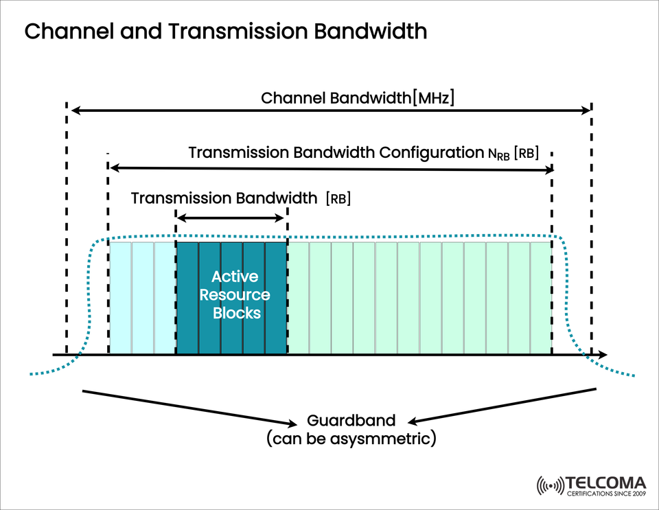
The image above shows the difference and connection between these important concepts, illustrating how channel bandwidth covers the whole allocated spectrum, while transmission bandwidth highlights the part actively in use, where resource blocks handle user data.
Channel Bandwidth: The Spectrum Envelope
Channel bandwidth represents the total width of the frequency band assigned to a network operator by regulatory bodies like the FCC or ITU. Measured in megahertz (MHz), it determines the maximum spectrum capacity available for transmission.
Key Points:
Unit: MHz
Purpose: Outlines the total available spectrum for communication.
Examples: 5 MHz, 10 MHz, and 20 MHz for LTE; up to 400 MHz for 5G NR in FR2 (mmWave).
Includes:
Active transmission area
Guard bands on both sides to reduce interference.
Role in Network Design
Sets the maximum throughput potential.
A broader channel bandwidth allows for higher data capacity and more users at once.
Operators can aggregate multiple channels (Carrier Aggregation) to boost effective bandwidth.
Transmission Bandwidth: The Active Transmission Zone
While channel bandwidth refers to the entire spectrum block, transmission bandwidth points to the part of the spectrum that actually carries user data and control signals.
In LTE and 5G, transmission bandwidth is defined by Resource Blocks (RBs). Each RB is made up of a set number of subcarriers in the frequency domain and time slots in the time domain.
In the Image:
You can observe that the Transmission Bandwidth Configuration (NRB [RB]) is smaller than the Channel Bandwidth — this shows real-world scenarios, as guard bands limit the usable segment.
Why Transmission Bandwidth Is Smaller
Guard bands help stop interference with nearby channels.
Hardware limits and regulations can shrink the effective transmission area.
Spectrum shaping preserves signal quality and adheres to emission masks.
Typical Configurations (LTE example):
Channel Bandwidth (MHz) | Transmission Bandwidth Configuration (NRB) | Transmission Bandwidth (MHz)
1.46 RBs ~ 1.08
15 RBs ~ 2.75
25 RBs ~ 4.510
50 RBs ~ 9.0
100 RBs ~ 18.0
In 5G NR, the conversion between MHz and RBs varies based on Subcarrier Spacing (SCS), which can be 15, 30, 60, 120, or 240 kHz.
- Resource Blocks (RBs): The Building Blocks of Transmission
Resource Blocks are the smallest allocatable units of bandwidth in the frequency domain. They're the foundational structure for data transmission in LTE and 5G NR.
Structure:
One RB = 12 subcarriers × 1 slot (0.5 ms in LTE or 1 slot duration in 5G NR, depending on numerology).
Each subcarrier has a fixed spacing (15 kHz in LTE; scalable in NR).
Active Resource Blocks:
In the diagram, the Active Resource Blocks are highlighted within the transmission bandwidth. These RBs handle:
User Data (PDSCH / PUSCH)
Control Information (PDCCH / PUCCH)
Reference Signals (RS / DMRS)
Inactive RBs might exist at the edges of the transmission bandwidth or during scheduling gaps to prevent interference from adjacent channels.
Guard Bands: Protecting Signal Integrity
Guard bands are frequency buffers placed at the edges of the channel bandwidth. They are vital in avoiding intermodulation distortion and spectral leakage into bordering channels.
Characteristics:
Generally asymmetric, as shown in the image.
Can change based on the frequency band, transmit power, and device type.
Don’t carry any active data or control signals.
Functionality:
Decrease interference from adjacent channels.
Allow flexible coexistence of various systems (like LTE and NR sharing nearby bands).
Ensure compliance with spectrum emission masks set by regulatory standards.
The Relationship Between Channel and Transmission Bandwidth
Here’s a quick summary of how these parameters relate:
Parameter | Definition | Unit | Role
Channel Bandwidth | Total allocated spectrum including guard bands | MHz | Spectrum capacity limit
Transmission Bandwidth | Portion of the channel used for actual transmission | RB or MHz | Active data-carrying zone
Active Resource Blocks | Subset of transmission bandwidth used for specific data transmission | RB | Determines data throughput
Guard Bands | Non-transmitting edges to prevent interference | MHz | Spectrum protection
This structured hierarchy helps wireless networks maintain high performance and spectral efficiency.
In 5G NR: Advanced Flexibility
5G offers greater flexibility in how bandwidth is used, thanks to Scalable Numerology and Bandwidth Parts (BWPs).
Key 5G Enhancements:
Scalable subcarrier spacing (15–240 kHz) allows adaptation across low and high frequency ranges.
BWPs enable UEs (User Equipment) to function on smaller active bandwidths within the overall channel bandwidth, which cuts down on power usage.
Dynamic bandwidth allocation lets networks shift resources based on needs.
This flexibility means 5G can function across a broad frequency range (from 450 MHz to 52 GHz), catering to a variety of applications from IoT to enhanced mobile broadband (eMBB).
Impact on Network Performance
Grasping and managing these bandwidth components directly influences:
Spectral efficiency — how effectively a system uses its spectrum.
Throughput — more RBs mean faster data rates.
Energy efficiency — a smaller active bandwidth leads to lower power use.
Interference management — guard bands and suitable configurations enhance network coexistence.
Optimization Strategies:
Make use of Carrier Aggregation to combine multiple transmission bandwidths.
Use Dynamic Spectrum Sharing (DSS) to effectively allocate resources between LTE and 5G.
Adjust power spectral density (PSD) to achieve optimal edge performance.
- Visualization Summary (Referring to the Image)
The image clearly shows:
The Channel Bandwidth (total frequency block).
The Transmission Bandwidth Configuration (NRB) found within it.
The Active Resource Blocks — the actual data transmission zones.
Guard bands, which may be asymmetric and inactive.
This visual representation helps engineers realize that not all allocated spectrum is utilized for data; some is set aside to maintain signal quality and adhere to regulatory standards.
Conclusion
The ideas behind Channel Bandwidth, Transmission Bandwidth, and Resource Blocks are fundamental to wireless communication systems like LTE and 5G NR.
Channel Bandwidth sets the outer limits of the spectrum.
Transmission Bandwidth indicates the usable area within that limit.
Resource Blocks determine how that bandwidth is put to work for data transmission.
Guard Bands ensure the system stays free from interference.
For telecom engineers and enthusiasts, understanding these distinctions is key to designing, optimizing, and keeping high-performance wireless networks running smoothly. As 5G continues to expand its spectrum usage, mastering these aspects of bandwidth management will be essential for achieving the promised levels of capacity, reliability, and efficiency in next-generation communication systems.