
Understanding Cross-Band Interference in 5G Networks: Causes, Harmonics, and Mitigation

Cross-Band Interference in 5G Networks: Causes, Effects, and Mitigation
As 5G technology keeps growing, operators are rolling out networks across a wider range of frequency bands, spanning from sub-GHz to millimeter wave. This extensive spectrum usage brings along new challenges in RF coexistence, where signals from one frequency band might unintentionally interfere with another.
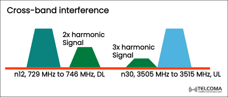
A significant issue here is cross-band interference, which happens when harmonics or spurious emissions from one band interfere with another band’s uplink or downlink spectrum. The diagram provided by Tel coma offers a clear look at this problem, illustrating how signals in the n12 band (729–746 MHz) can create harmonic interference impacting the n30 band (3505–3515 MHz).
Let’s dive into how this interference occurs, what it means for 5G networks, and the engineering solutions that can help mitigate it.
What Is Cross-Band Interference?
Cross-band interference happens when unwanted signals created in one frequency band—often due to nonlinearities in radio hardware—spill over into another frequency band used for communication.
These unwanted emissions typically come from:
Harmonics (integer multiples of a fundamental signal frequency)
Intermodulation products (mixing multiple signals)
Spurious emissions (unwanted radiation from transmitters)
When these signals overlap with another band’s uplink (UL) or downlink (DL) frequencies, it can seriously hinder network performance.
Understanding the Diagram
The image outlines a practical example of cross-band interference between two 5G NR frequency bands:
Band Frequency Range Direction Interference Typen12729 MHz – 746 MHz Downlink (DL)Source of harmonic emissionsn303505 MHz – 3515 MHz Uplink (UL)Victim of interference
Here’s how it plays out:
The base station sends downlink signals in band n12 (729–746 MHz).
Because of nonlinear behavior in RF components like power amplifiers, these signals generate harmonics — multiples of the original frequencies: * The 2nd harmonic happens at 2 × 729–746 MHz = 1458–1492 MHz * The 3rd harmonic happens at 3 × 729–746 MHz = 2187–2238 MHz
In this example, certain harmonic products (like the 3rd harmonic) fall close to the n30 uplink band around 3.5 GHz.
This overlap leads to cross-band interference, which interferes with uplink reception at the base station (gNB).
The Role of Harmonic Signals
Harmonics are integer multiples of the fundamental signal frequency. For instance:
1st harmonic = original frequency (f)
2nd harmonic = 2f
3rd harmonic = 3f
Though higher-order harmonics usually carry lower power levels, their effect depends on:
Proximity of affected bands
Receiver sensitivity
Power level of the interfering signal
Even a low-power harmonic can cause significant interference if it lands in a sensitive uplink band operating at microvolt-level signal strengths.
How Cross-Band Interference Impacts 5G Networks
- Uplink Noise Floor Increase
When harmonic emissions from downlink signals seep into uplink frequencies, the noise floor at the base station receiver rises. This diminishes uplink sensitivity, leading to:
Poor signal-to-noise ratio (SNR)
Reduced data throughput
More retransmissions
- Reduced Coverage
With uplink reception quality declining, cell coverage shrinks. User equipment (UE) might struggle to connect from greater distances, especially in low-SNR situations.
- Scheduler and QoS Impacts
The base station’s scheduler may have to allocate extra resources to make up for errors, which can lower overall network efficiency and degrade Quality of Service (QoS).
- Hardware Performance Issues
Ongoing interference could push RF front-end components (like LNA and filters) to operate near saturation, potentially speeding up hardware aging or causing thermal instability.
Causes of Cross-Band Interference
- Nonlinear RF Components
Power amplifiers (PAs), mixers, and frequency multipliers exhibit nonlinearities that lead to harmonics and intermodulation products.
- Inadequate Filtering
If transmitter filters aren’t good enough to block harmonic frequencies, those harmonics can leak into nearby or distant bands.
- Shared Antenna Systems
In multi-band systems using common antennas or combiners, inadequate isolation can lead to harmonic coupling between paths.
- Poor Frequency Planning
When network planners assign frequency bands that are harmonic multiples of each other (for example, 700 MHz × 5 = 3500 MHz), the risk of cross-band interference rises significantly.
Real-World Example: n12 and n30 Coexistence
The n12 band (729–746 MHz) and n30 band (3505–3515 MHz) present a real-world interference situation.
The downlink in n12 generates 2nd and 3rd harmonic signals.
If these harmonics aren't filtered out, they can overlap with the uplink of n30.
Given that uplink signals are sent from user devices at lower power levels (typically +23 dBm or less), strong base station downlink transmissions can easily overpower the uplink channel.
This means that even if the user’s device is sending a proper signal, the base station might struggle to decode it, mistaking the harmonic noise for part of the uplink spectrum.
Engineering Techniques to Mitigate Cross-Band Interference
Telecom engineers have a few strategies to reduce or eliminate these issues:
- RF Filtering
Use low-pass, band-pass, or notch filters to cut down harmonics before they reach the antenna.
Implement high-Q cavity filters for sharp roll-off characteristics.
- Spectrum Planning and Band Selection
Be cautious about assigning frequency bands whose harmonics overlap with active uplink or downlink bands.
Use frequency offset analysis tools during spectrum planning to spot risky pairings.
- Improved Component Linearity
Design RF front ends with high linearity (low IMD — Intermodulation Distortion).
Use Digital Predistortion (DPD) in power amplifiers to counteract nonlinearities.
- Physical Separation
Increase physical distance between transmit and receive antennas for bands with harmonic relationships.
Use directional antennas to minimize coupling.
- Uplink Scheduling and Filtering at gNB
Apply adaptive digital filtering at the gNB receiver to eliminate certain harmonic patterns.
Temporarily avoid scheduling uplink transmissions in frequencies known to overlap with harmonics.
Cross-Band Interference in 5G vs. LTE
While cross-band interference isn't a new problem, 5G brings new challenges because:
More bands (sub-6 GHz, mm Wave) are used at the same time.
Dynamic Spectrum Sharing (DSS) adds to the complexity.
Higher transmit powers and broader bandwidths increase harmonic generation.
In LTE, spectrum allocation was generally tighter, lowering the chances of overlapping harmonics. With 5G’s massive carrier aggregation (CA) and multi-band operations, the likelihood of harmonic overlaps increases.
Testing and Validation for Cross-Band Interference
- Spectrum Analysis
Utilize high-resolution spectrum analyzers to find harmonic peaks and their power levels compared to the carrier.
- Intermodulation Testing
Inject known signals into the system and measure IMD products to evaluate component linearity.
- Radiated Emissions Testing
Conduct over-the-air (OTA) measurements in shielded chambers to confirm real-world emission characteristics.
- Coexistence Simulation
Simulate multiple carrier operations to predict harmonic overlap zones before deployment.
Summary Table: Cross-Band Interference Overview
Aspect Description Phenomenon Harmonics or spurious emissions from one band interfering with another Typical Cause Nonlinear RF components, poor filtering Affected Bands Bands with harmonic frequency relationships Impact Reduced uplink sensitivity, higher noise floor Mitigation Filtering, linear amplifiers, careful frequency planning
Conclusion
Cross-band interference is one of the hidden complexities in today’s 5G networks, where numerous frequency bands coexist to deliver ultra-fast connectivity. As the diagram demonstrates, harmonics generated from one band’s downlink (like n12) can easily overlap another band’s uplink (like n30), leading to performance and reliability issues.
By using robust filtering, enhancing linearity, thoughtful frequency planning, and coexistence testing, engineers can tackle these problems and maintain clear, interference-free communication channels.
In a world where spectrum is a limited and valuable resource, understanding and managing cross-band interference is crucial for unlocking the full potential of 5G and beyond.