
Understanding CUPS Architecture for EPC: Enhancing 4G and 5G Core Network Efficiency

CUPS Architecture for EPC: A New Era of Network Efficiency and Flexibility
The telecom industry has changed quite a bit due to the rapid increase in data traffic, IoT connectivity, and the need for low-latency applications. To tackle these challenges, we got CUPS (Control and User Plane Separation), which is now part of the Evolved Packet Core (EPC) — basically the backbone of LTE networks.
This new architecture lets operators scale, optimize, and modernize their networks more effectively by splitting the control plane (C-plane) and user plane (U-plane) functions. This is a crucial step towards designing the 5G Core (5GC).
What is the CUPS Architecture in EPC?
CUPS, or Control and User Plane Separation, was formalized by 3GPP (Release 14) to improve the traditional EPC setup. In the classic EPC model, both control and user plane functions exist in the same network components, which can limit scalability and create inefficiencies during traffic spikes.
By separating these two planes, operators can scale them independently, deploy user planes nearer to the edge for reduced latency, and make network upgrades easier without disrupting ongoing services.
Key CUPS Goals
Flexibility: Scaling of control and user planes independently.
Efficiency: Better use of resources and less signaling overhead.
Low Latency: Positioning user planes near users or at the network's edge.
Evolution Readiness: A smooth transition path to 5G Core network architecture.
Core Components of CUPS in EPC
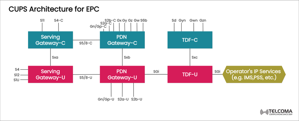
The CUPS architecture lays out a clear distinction between the control plane (C) and user plane (U) functions across critical EPC elements — Serving Gateway (SGW), PDN Gateway (PGW), and Traffic Detection Function (TDF).
The diagram highlights three control-user plane pairs:
Control Plane Entity User Plane Entity Interface Serving Gateway-C (SGW-C)Serving Gateway-U (SGW-U) SxaPDN Gateway-C (PGW-C)PDN Gateway-U (PGW-U) SxbTDF-C (Traffic Detection Function-C)TDF-U (Traffic Detection Function-U)Sxc
Each control node is responsible for managing policies, signaling, and session control, while their corresponding user plane nodes take care of actual data forwarding and routing.
Detailed Functional Overview
- Serving Gateway (SGW-C and SGW-U)
SGW-C (Control Plane): Manages control signaling for bearer management, handovers, and session setups. Interfaces like S11 allow it to connect with the MME, while S5/8-C links it to the PGW-C.
SGW-U (User Plane): Forwards user data packets between eNodeB (via S1-U) and the PDN Gateway (via S5/8-U). It can be placed closer to the edge of the network to minimize latency.
Interface: The Sxa interface links SGW-C and SGW-U, passing control signaling for user plane management.
- PDN Gateway (PGW-C and PGW-U)
PGW-C (Control Plane): Responsible for IP address allocation, enforcing policies, and charging. It connects with other systems using Gx, Gy, Gz, and S6b interfaces to work with PCRF and AAA servers.
PGW-U (User Plane): Directs user traffic between the EPC and external IP networks, such as the internet or corporate intranets. It operates at the SGi interface and handles packet filtering, NAT, and QoS tasks.
Interface: The Sxb interface ensures PGW-C controls the behavior of PGW-U dynamically.
- Traffic Detection Function (TDF-C and TDF-U)
TDF-C (Control Plane): Manages traffic detection based on applications and policy enforcement, often collaborating with the PCRF for smarter traffic shaping.
TDF-U (User Plane): Looks at traffic in real-time for deep packet inspection (DPI) and content optimization.
Interface: The Sxc interface connects TDF-C and TDF-U for traffic filtering and content control coordination.
Operator’s IP Services
Once user traffic flows through the PGW-U and TDF-U, it exits through the SGi interface to access operator-specific IP services like:
IMS (IP Multimedia Subsystem) for VoLTE/VoWiFi
PSS (Packet-Switched Streaming) for video and content delivery
External IP networks or corporate VPNs
This setup ensures traffic gets to its destination efficiently, optimizing routing and cutting down on latency.
How CUPS Enables Network Optimization
CUPS isn’t just a tweak in architecture — it’s a strategic upgrade that lets operators create scalable, flexible, and cloud-native networks.
Here’s how it enhances network operations:
- Independent Scaling
Control and user planes can grow separately according to demand. For instance, if there’s a high signaling load, scaling SGW-C/PGW-C can handle it, whereas data-heavy needs can be met by scaling SGW-U/PGW-U.
- Edge Deployment
User plane nodes (SGW-U, PGW-U) can be placed nearer to subscribers — at mobile edge sites — which significantly cuts down latency and boosts performance for real-time apps like AR/VR and IoT.
- Centralized Control
All control functions stay centralized, providing better visibility, enforcement of policies, and resource management across distributed user plane nodes.
- Cloud-Native Readiness
CUPS sets the stage for virtualization and NFV-based setups, allowing operators to run control and user plane functions as virtualized network functions (VNFs) on cloud infrastructure.
CUPS Interfaces and Protocols Summary
Interface Connection Function SxaSGW-C ↔ SGW-U Control signaling for SGW user plane Sxb PGW-C ↔ PGW-U Control signaling for PGW user plane SxcTDF-C ↔ TDF-U Policy and traffic detection coordinationS11, S5/8-CMME ↔ SGW-C ↔ PGW-C Session control and mobility managementS1-U, SGiSGW-U ↔ PGW-U ↔ IP Services User data forwarding
This structured communication guarantees seamless coordination between all EPC elements and external IP service domains.
Benefits of Implementing CUPS in EPC
Benefit Description Reduced Latency User planes at the edge reduce data paths for time-sensitive services. Enhanced Scalability Independent scaling of control and user functions supports massive IoT growth. Operational Efficiency Eases network maintenance and upgrades. Cloud Integration Setups EPC for NFV/SDN and 5G core evolution. Cost Optimization Better resource use lowers CAPEX/OPEX.
CUPS as the Bridge to 5G Core
Though CUPS is part of LTE EPC, it signals a transitional architecture toward 5G. The 5G Core (5GC) fully adopts service-based architecture (SBA) and cloud-native principles, building on the control and user plane separation that CUPS started.
By putting CUPS into play in EPC, operators stand to:
Kick off edge computing initiatives
More easily roll out network slicing
Seamlessly interact with 5GC via Non-Standalone (NSA) configurations
Conclusion
The CUPS architecture for EPC is a significant milestone in the evolution of telecom networks, enabling operators to handle the increasing demands for data traffic with agility, scalability, and accuracy.
By decoupling control and user planes, CUPS not only boosts LTE performance but also lays the groundwork for next-generation 5G networks and cloud-native architectures.
Understanding and implementing CUPS is crucial for telecom professionals and network architects to ensure networks are future-proof, deliver low-latency experiences, and drive next-level digital innovation.