
Understanding gNB Logical Architecture in 3GPP for 5G Networks

As 5G rolls out, network architecture has changed a lot to keep up with the high demands for speed, latency, reliability, and scalability. A key innovation from the 3GPP (3rd Generation Partnership Project) is the logical split of the gNB (Next Generation NodeB) into different functional parts.
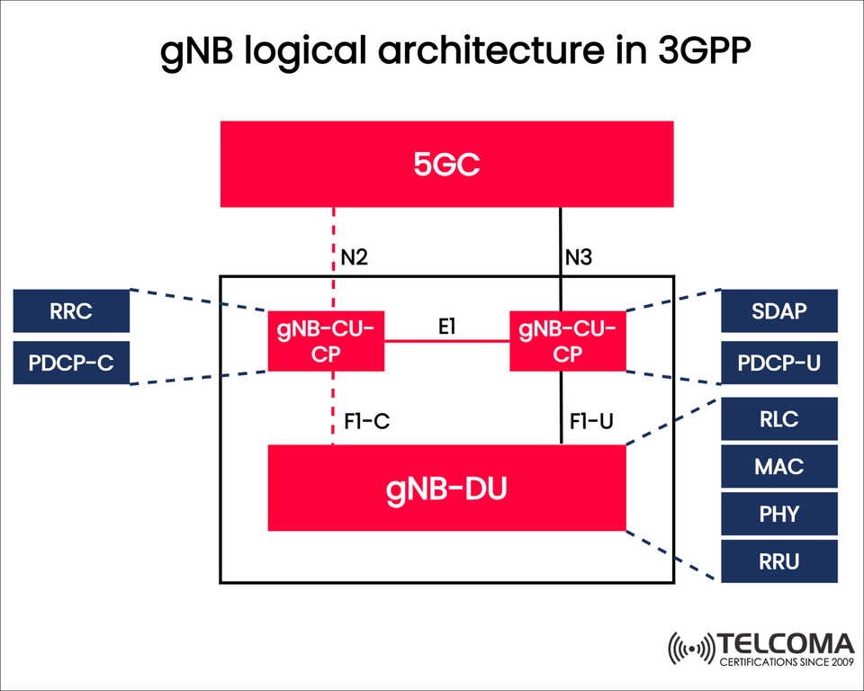
This new gNB logical architecture allows operators to set up 5G networks with more flexibility, better resource management, and future-ready scalability. The diagram that’s been provided shows how the gNB-CU (Central Unit), gNB-DU (Distributed Unit), and 5G Core (5GC) are all connected, detailing control and user plane functions.
In this guide, we’ll break down the architecture, clarify the roles of each component, and relate these ideas to real-world 5G use cases.
What is gNB in 5G?
So, in the 5G world, the gNB is the counterpart to the LTE eNodeB (eNB), but it comes with added flexibility. Unlike LTE where the eNB was just a single logical unit, 5G gNB is divided into several units for enhanced scalability and performance.
gNB = Central Unit (CU) + Distributed Unit (DU)
These pieces talk to each other using standardized interfaces set by the 3GPP.
This division lets operators spread computing tasks between central cloud systems and local radio sites.
The gNB Logical Architecture
The diagram illustrates how the gNB architecture is divided into logical components:
- gNB-CU (Central Unit)
Generally located in the cloud or a central hub.
Takes care of higher-layer protocols and functions that don’t need real-time processing.
It’s divided into two logical parts: * gNB-CU-CP (Control Plane): * Deals with signaling and control (RRC, PDCP-C). * Connects to the 5GC via N2. * gNB-CU-UP (User Plane): * Manages data traffic (SDAP, PDCP-U). * Connects to the 5GC using N3.
Advantage: This setup allows operators to scale control and user planes separately, boosting performance for varying scenarios.
- gNB-DU (Distributed Unit)
Usually found at cell sites or edge locations.
Manages lower-layer protocols needing real-time processing: * RLC (Radio Link Control) * MAC (Medium Access Control) * PHY (Physical Layer) * RRU (Remote Radio Unit) for RF operations
Links to the CU via F1-C (control plane interface) and F1-U (user plane interface).
Advantage: Keeping time-sensitive functions closer to the radio means lower latency.
- 5G Core (5GC)
Connects to the gNB-CU: * N2 Interface: Handles signaling/control. * N3 Interface: Manages user plane traffic.
Basically the brain of the network—covering mobility, session management, authentication, and policy control.
Protocol Stack in gNB
The logical split also indicates which protocol layers CU and DU control.
Component Protocols Handled Plane gNB-CU-CPRRC, PDCP-C Control Plane gNB-CU-UPSDAP, PDCP-U User Plane gNB-DURLC, MAC, PHY, RRUControl + User Plane
This arrangement ensures optimal processing placement: non-real-time functions are centralized, while latency-critical functions stay distributed.
Interfaces in gNB Logical Architecture
The split comes with a few key interfaces:
E1: Links gNB-CU-CP and gNB-CU-UP.
F1-C: Control interface between CU-CP and DU.
F1-U: User plane interface linking CU-UP and DU.
N2: Control interface connecting CU-CP and 5GC.
N3: User plane interface connecting CU-UP and 5GC.
These interfaces are standardized by 3GPP, making multi-vendor interoperability a reality—which is essential for Open RAN setups.
Why Split gNB into CU and DU?
The split for gNB wasn’t just a random decision. It was made to meet new 5G demands:
Scalability: CU and DU can scale independently, adapting to varying traffic loads.
Deployment Flexibility: CU can reside in central data hubs, while DUs stay closer to cell sites.
Low Latency: Offloading real-time functions to DUs helps 5G hit that 1 ms latency target for URLLC.
Cost Efficiency: Centralization simplifies site operations and reduces costs.
Support for Multiple Use Cases: eMBB, URLLC, and mMTC can all run together by dynamically shifting resources.
Real-World Use Cases of gNB Split Architecture
Dense Urban Deployments: CU in the metro core coupled with DUs at cell towers for enhanced coordination.
Rural Networks: Fewer DUs covering wide areas, with centralized CUs to keep costs down.
Private 5G Networks: Businesses use on-premise DUs for latency-sensitive tasks, with CU functions often in a private cloud.
Open RAN (O-RAN): This architecture sets the stage for disaggregated, multi-vendor networks, encouraging innovation and cutting costs.
Benefits of gNB Logical Architecture
✅ Boosted network efficiency through better resource allocation.
✅ Reduced latency for crucial applications.
✅ Cloud-native deployments are feasible for CU functions.
✅ Vendor interoperability thanks to standardized interfaces.
✅ Scalability for future needs as traffic increases.
Challenges of CU/DU Split
Yet, this split isn't without its challenges:
Needs synchronization between CU and DU.
Transport network reliance: F1 interface requires high capacity and low latency.
Operational complexity when managing distributed units.
Vendor interoperability hurdles in practice, even with standards.
A Closer Look: Control Plane vs User Plane in gNB
One of the key features of the gNB logical split is how it separates the Control Plane (CP) from the User Plane (UP).
Control Plane (gNB-CU-CP):
Handles signaling, mobility, and setting up sessions.
Utilizes RRC (Radio Resource Control) to manage and configure UE connections.
Takes care of handover management to ensure smooth transitions between cells.
Collaborates with PDCP-C for important security tasks like encryption and integrity protection.
User Plane (gNB-CU-UP):
Deals with the actual user data traffic like video streams, web browsing, VoIP, and more.
Incorporates SDAP for mapping Quality of Service (QoS) and PDCP-U for tasks like header compression, ciphering, and data transfer.
Designed for maximizing throughput and efficiency, keeping signaling to a minimum.
This separation of CP and UP is essential for network slicing. It allows operators to customize the control and user planes for various slices, such as one that’s optimized for IoT.
Conclusion
The gNB logical architecture from 3GPP marks a major shift in RAN design. By splitting functions between the Central Unit (CU) and the Distributed Unit (DU), operators get the flexibility, scalability, and performance boosts they need for the varied demands of 5G.
CU tackles higher-layer, non-real-time functions.
DU handles real-time, latency-sensitive tasks right at the edge.
5GC connects the RAN to the core, making 5G services work from end to end.
For those in telecom, wrapping your head around this split is key for 5G deployment strategies, embracing Open RAN, and anticipating future 6G advancements.