
Understanding Handover Interruption Time in 5G Networks: Source and Target Cell Data Flow Explained

Understanding 5G Handover Interruption Time: Coordination Between Source and Target Cells
When mobile users navigate through a network, keeping a smooth connection while transitioning between cells is essential. This process, commonly referred to as handover (HO), ensures that things like voice calls or streaming don’t get interrupted.
Yet, even the most sophisticated 5G systems face a brief moment where data transfer stops. This moment is called Handover Interruption Time (HIT).
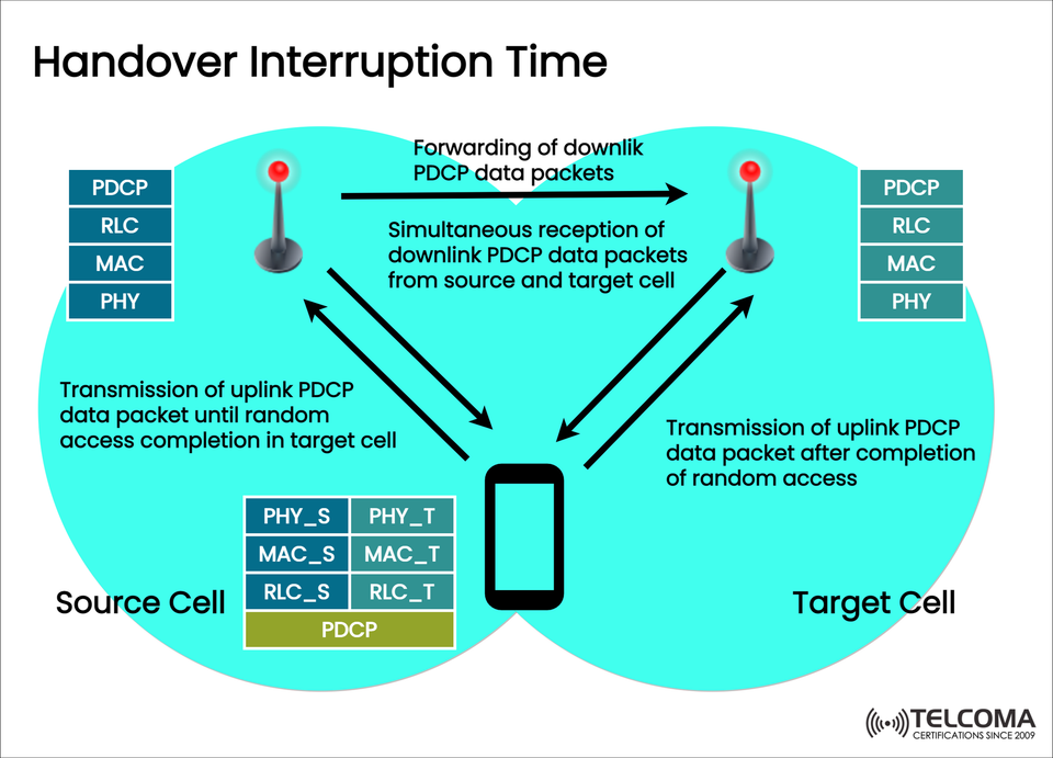
In this article, we’ll explore the handover interruption process depicted in the image above, focusing on aspects like PDCP data forwarding, uplink and downlink transitions, and the protocol stack interactions between the source and target cells.
What Is Handover Interruption Time?
Handover Interruption Time (HIT) is the period when a user device (UE) can’t send or receive user-plane packets while switching from one cell to another.
It usually happens between when the UE disconnects from the source cell and when it successfully connects to the target cell.
In simpler terms:
It's that brief pause in communication that takes place while your phone connects to a new base station when you’re on the move.
Why Handover Interruption Time Is Important
Reducing HIT is crucial for making sure:
Voice and video calls remain uninterrupted
Streaming experiences are smooth
Low-latency applications like gaming or AR/VR stay stable
Vehicles and IoT devices on the go maintain reliable connectivity
The goal for 5G is to keep HIT below 20 milliseconds, allowing for ultra-reliable low-latency communication (URLLC).
Protocol Layers Involved in Handover
Before we jump into the sequence, let’s recap the key protocol layers shown in the diagram — part of the 5G NR user plane stack:
Layer | Full Name | Function
PDCP | Packet Data Convergence Protocol | Deals with header compression, encryption, and reordering
RLC | Radio Link Control | Manages segmentation, reassembly, and retransmission
MAC | Medium Access Control | Schedules radio resources and multiplexes logical channels
PHY | Physical Layer | Sends actual radio signals over the air
During a handover, all these layers play a key role in forwarding, buffering, and retransmitting packets.
Overview of Handover Interruption Time Sequence
The image highlights what happens between:
Source Cell (the current serving g Node B)
Target Cell (the new g Node B)
User Equipment (UE)
Here’s the step-by-step breakdown:
- Sending Uplink PDCP Packets (Before Handover Completion)
While still connected to the source cell, the UE keeps sending uplink PDCP data packets until the random access procedure in the target cell wraps up.
The source PDCP layer keeps the uplink flow ongoing.
Lower layers (RLC_S, MAC_S, PHY_S) make sure the data reaches the g Node B.
Once the handover command comes through, the UE gets ready to sync with the target cell.
This setup ensures that no uplink packets get lost in the early stages of the handover.
- Forwarding Downlink PDCP Data Packets
To avoid dropping packets, the source cell sends downlink PDCP packets to the target cell.
These packets have the remaining buffered data that hasn’t reached the UE yet.
The target cell temporarily holds these packets until it's ready to deliver them to the UE after the random access phase.
This process ensures downlink data continuity without needing retransmission from the core network.
- Receiving Downlink PDCP Packets Simultaneously
During the handover, the UE can receive downlink PDCP packets from both:
Source cell (the connection is still active)
Target cell (the new link is being established)
This overlapping time guarantees a soft continuity of service and reduces the chance of data loss. It’s particularly important in Make-Before-Break situations (like Dual Connectivity or Conditional Handover in 5G).
- Completing Random Access in Target Cell
Once the random access procedure (RACH) in the target cell finishes, the UE officially connects to the new cell.
The PHY_T and MAC_T layers get uplink synchronization set up.
The RLC_T and PDCP layers begin processing new user-plane packets.
The UE lets the target g Node B know that it’s accessed successfully.
At this stage, the handover interruption time effectively concludes, and normal data transmission picks back up.
- Sending Uplink PDCP Packets via Target Cell
After completing random access:
The UE starts sending uplink PDCP packets through the target cell.
The connection with the source cell is dropped.
The PDCP entity carries on in the target cell, keeping the same sequence numbers to ensure packets stay ordered.
From this point on, data flow resumes fully in both uplink and downlink directions.
Technical Breakdown of Handover Interruption Components
Phase | Process | Duration Impact
Pre-Handover | PDCP forwarding setup | Negligible
Execution | RACH procedure + synchronization | Major contributor
Post-Handover | Buffer reordering and ACKs | Minor contributor
The random access procedure and the RLC re-establishment typically take the most time. Fine-tuning these steps can help cut down the overall interruption time.
Handover Interruption in Different 5G Scenarios
- Intra-g Node B Handover
Both source and target cells are within the same g Node B.
HIT is minimal (<5 ms) since PDCP remains unchanged.
- Inter-g Node B Handover (Within Same 5GC)
PDCP might need to move; forwarding happens.
HIT goes up slightly (~10–20 ms).
- Inter-System Handover (5G to LTE or vice versa)
Calls for a full context switch and NAS signaling.
HIT can go beyond 50 ms, depending on backhaul latency.
Cutting Down Handover Interruption Time in 5G
Telecom engineers and vendors use various methods to lower HIT:
a. PDCP Duplication
Sending the same PDCP packet over multiple radio links boosts reliability, ensuring at least one copy makes it to the UE.
b. Conditional Handover (CHO)
UEs can set up target cells ahead of time and execute handover on their own based on specific conditions (like RSRP/RSRQ thresholds), cutting down delay.
c. Dual Connectivity (EN-DC or NR-DC)
UEs can stay connected to multiple cells at once, which allows for “make-before-break” handovers.
d. Optimized RACH Procedures
Reducing contention and the preamble wait time during random access enhances switchover efficiency.
e. Edge Computing Support
Bringing user-plane functions closer to the radio edge cuts down on backhaul delay during PDCP forwarding.
Real-World Example:
Imagine a 5G user streaming video while moving between two NR cells.
The UE stays linked to the source cell, sending uplink packets.
As the signal fades, the target cell is readied through RRC signaling.
Downlink packets are forwarded and buffered by the target.
Once random access is successful, the UE resumes transmission — and the video stream carries on without a hitch.
In a well-optimized network, this interruption is so brief (10–20 ms) that it becomes nearly undetectable for the user.
Key Metrics Operators Keep An Eye On
Metric | Description | Target (5G NR)
Handover Interruption Time (HIT) | Time without data transfer | < 20 ms
Handover Success Rate | Successful handovers / total attempts | > 98%
RACH Success Rate | Successful random access in target cell | > 99%
Packet Loss during HO | Data lost during transition | < 0.1%
Keeping track of these KPIs helps operators maintain seamless mobility and ensure a great Quality of Experience (QoE) for users.
Wrapping Up
Handover Interruption Time is an essential performance metric in 5G mobility management, representing that brief pause when the UE switches from one cell to the next.
As illustrated:
PDCP data forwarding,
Simultaneous downlink reception, and
Completing random access
are all vital for smooth, low-latency transitions between source and target cells.
Thanks to advanced strategies like PDCP duplication, dual connectivity, and conditional handover, 5G networks are quickly moving towards almost zero interruption times, paving the way for truly seamless mobility for real-time and mission-critical applications.
In a world of autonomous vehicles, industrial IoT, and immersive media, cutting down HIT isn’t just a performance target — it’s a must for our connected future.