
Understanding OTN Network Interconnections: UNI, NNI, and MNI Explained

The Connections Between Users and the OTN Network
Nowadays, in fast and reliable carrier-grade networks, it’s crucial for users, network operators, and equipment providers to be interconnected seamlessly. The Optical Transport Network (OTN), as standardized by the ITU-T G.709 series, gives us a structured and interoperable framework for optical transmission.
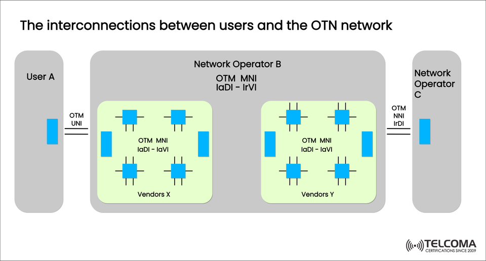
The diagram we uploaded — “The interconnections between users and the OTN network” — shows how users, operators, and vendor domains interact through standard OTN interfaces like UNI, NNI, and MNI. This model allows multi-operator and multi-vendor environments to work together smoothly across extensive optical infrastructures.
In this article, we’ll go through each part of the diagram, explain what these interfaces do, and show how OTN ensures everything works well and scales up in today’s telecom systems.
Introduction to Optical Transport Network (OTN)
The Optical Transport Network (OTN) is a digital framework that efficiently handles a variety of client signals — things like Ethernet, SDH, Fibre Channel, and IP/MPLS — as they travel over optical fiber.
OTN not only sets the rules for how data gets wrapped and sent but also explains how different network domains and pieces of equipment fit together. This is done using standard interfaces such as:
OTM UNI (User Network Interface)
OTM NNI (Network Node Interface)
OTM MNI (Multiple Network Interface)
These interfaces work to ensure that signal transmission, management, and interoperability run smoothly across users, operators, and vendors.
Understanding the Diagram: The Interconnection Model
The diagram illustrates interactions between:
User A
Network Operator B (Core OTN Network)
Network Operator C
Vendor domains (X and Y)
Let’s dig into it layer by layer.
User A and OTN UNI
On the left side, User A connects to the OTN network via the OTM UNI (User-Network Interface).
OTM UNI (Optical Transmission Module User Network Interface) marks the boundary between a user’s network and the operator’s OTN domain.
Key Features of OTM UNI:
Acts as the service demarcation point between the user and the provider.
Ensures user traffic gets properly mapped into OTN frames (think ODUk/OTUk).
Allows for service provisioning, monitoring, and fault isolation.
Example:
A data center operator (User A) connects to a telecom service provider’s OTN backbone (Network Operator B) using UNI. It might carry a 100GbE client signal that’s mapped into an ODU4 frame.
Inside the OTN Core: OTM MNI
Within Network Operator B’s domain, we see two vendor sub-networks — Vendor X and Vendor Y.
These vendor domains communicate through OTM MNI (Multiple Network Interface) connections.
Definition:
OTM MNI (OTM Multi-Network Interface) describes how different vendor equipment or technology domains interconnect within the same operator’s network.
This setup assures vendor interoperability while keeping network management and performance intact.
Key Functional Areas:
IaDI – IaVI: Intra-domain interfaces for linking vendor elements (like Vendor X’s optical gear).
IrDI – IrVI: Inter-domain interfaces for connecting different vendor systems (for example, Vendor X ↔ Vendor Y).
Benefits of OTM MNI:
Lets operators mix different vendors’ optical hardware.
Supports network scalability and modular growth.
Eases testing and commissioning with standardized control signals.
Example:
In Network Operator B’s optical backbone, Vendor X's equipment (say, from Ciena) connects to Vendor Y's gear (like from Nokia) through an MNI interface. Both follow ITU-T G.709 standards for framing and OTN management to ensure they play nice together.
Between Operators: OTM NNI
Now, on the right side, Network Operator B connects to Network Operator C using OTM NNI (Network-to-Network Interface).
Definition:
OTM NNI specifies the interface between two different OTN networks or operators, enabling smooth optical service handovers and inter-domain connections.
Types of OTM NNI:
Internal NNI (IrDI – Internal Reference Data Interface) * Connects segments within the same operator, like different regions or divisions.
External NNI (IeDI – External Data Interface) * Used between different operators (e.g., Operator B ↔ Operator C).
Purpose of OTM NNI:
Ensures service continuity across network boundaries.
Keeps performance monitoring and fault localization in check.
Guarantees interoperability between operators’ OTN setups.
Example:
If Operator B has a backbone linking two cities, and Operator C extends that connection to another area, OTM NNI ensures both OTN networks can effortlessly exchange and manage optical services.
Summary of OTN Interface Types
Interface Type Full Form Interconnects Example Use Case OTM UNI User-Network Interface User ↔ Operator Data center ↔ Telecom provider OTM MNI Multi-Network Interface Vendor A ↔ Vendor B (same operator)Ciena ↔ Nokia within Operator BOTM NNI Network-to-Network Interface Operator A ↔ Operator B Inter-operator backbone connection
Each interface promotes service transparency, OAM (Operations, Administration, and Maintenance), and performance management to maintain dependable optical connectivity.
Understanding the Interface Identifiers (IaDI, IaVI, IrDI, IrVI)
The diagram labels the interfaces with specific identifiers. Here’s what they mean:
IaDI (Intra-domain Data Interface): Connects devices within the same vendor domain.
IaVI (Intra-domain Vendor Interface): Vendor-specific interface for internal connectivity.
IrDI (Inter-domain Data Interface): Connects two vendor or operator domains.
IrVI (Inter-domain Vendor Interface): Manages vendor transitions in multi-domain networks.
These identifiers help standardize and pinpoint where in the network an interface operates — which is vital for large-scale environments with multiple operators.
Multi-Vendor and Multi-Operator Scenarios
One of the biggest strengths of OTN is how well it handles multi-vendor and multi-operator scenarios with minimal interoperability hassles.
Multi-Vendor Benefits (within MNI):
Operators get to choose the best equipment from different vendors.
Avoids being locked into a single vendor.
Supports gradual tech upgrades.
Multi-Operator Benefits (with NNI):
Expands service coverage beyond one operator’s area.
Enables partnerships for optical transport on a global scale.
Facilitates end-to-end service orchestration.
Real-world example:
A global telecom provider can link customer traffic across multiple countries by connecting different national OTN networks via standardized NNI interfaces.
Importance of Standardization in OTN Interconnections
The standardization from ITU-T G.709 makes sure that all interfaces (UNI, NNI, MNI) keep:
Signal transparency
Frame structure integrity (ODUk, OTUk layers)
OAM compatibility (BIP-8, PM, TCM bytes)
Forward Error Correction (FEC) support
This guarantees that client data (like 100GbE, STM-64, or IP/MPLS) can move through various OTN networks without any changes, ensuring true end-to-end interoperability.
Advantages of the OTN Interconnection Model
End-to-End Transparency — Client data stays the same all through.
Scalability — Supports various bit rates and services.
Interoperability — Works between multiple vendors and operators.
Enhanced Manageability — Integrated OAM tools for tracking faults and performance.
Future-Proof — Adapts to new technologies like 400G and 800G transport.
Conclusion
The interconnection framework of OTN, as shown in the diagram, forms the foundation of modern optical networking. By establishing clear, standardized interfaces like UNI, MNI, and NNI, OTN allows for smooth communication between users, operators, and vendors.
In an era where networks stretch across continents and technologies evolve rapidly, this standardization ensures interoperability, scalability, and reliability — the critical pillars of the global telecom ecosystem.