
Understanding PDCCH Monitoring in 5G NR: CORESET, CCE, and REG Explained

Understanding PDCCH Monitoring in 5G NR: CORESET, CCE, and REG Explained
In 5G New Radio (NR), the Physical Downlink Control Channel (PDCCH) is crucial for sending downlink control info (DCI) to user equipment (UE). Unlike the fixed control structure in LTE, 5G brings a flexible and configurable control system using CORESETs (Control Resource Sets), CCEs (Control Channel Elements), and REGs (Resource Element Groups).
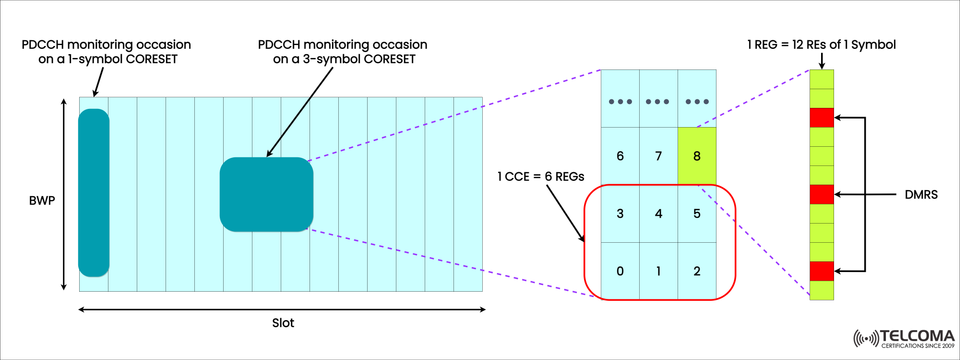
The image uploaded shows how PDCCH monitoring occasions happen over various CORESET durations (either 1-symbol or 3-symbol CORESETs), how CCEs are created from REGs, and the role of DMRS (Demodulation Reference Signals) in this setup.
Let’s dive into the details about the structure, mapping, and significance of these components.
- Overview of PDCCH in 5G NR
The PDCCH carries Downlink Control Information (DCI), which notifies the UE about:
Scheduling grants for PDSCH and PUSCH,
Power control instructions,
HARQ feedback,
Beamforming and MIMO configurations,
Resource assignments for both uplink and downlink.
In 5G NR, the PDCCH's structure and positioning aren't fixed like they were in LTE. Now, they’re dynamically configured through CORESETs, allowing network operators to fine-tune control signaling for various scenarios, from crowded urban macro cells to IoT-focused microcells.
- PDCCH Monitoring Occasion and CORESET Duration
As the image illustrates, PDCCH monitoring occasions can take place within a Bandwidth Part (BWP) and can vary:
A 1-symbol CORESET, or
A 3-symbol CORESET (or different lengths depending on configuration).
Each CORESET defines where and how long the PDCCH is sent within a slot.
Key Characteristics:
A CORESET comprises a collection of Resource Blocks (RBs) and OFDM symbols.
It’s configured using higher-layer parameters through RRC signaling.
The duration (in terms of OFDM symbols) can be from 1 to 3 symbols.
The frequency domain allocation is flexible, meaning a CORESET can occupy part or all of a BWP.
In the Image:
The left section features two monitoring occasions — one with a 1-symbol CORESET and another with a 3-symbol CORESET.
This flexibility means the network can adjust control signaling density based on channel conditions and UE needs.
- Hierarchical Structure: From CORESET to REGs
In each CORESET, PDCCH resources are organized hierarchically:
CORESET → REGs (Resource Element Groups)
REGs → CCEs (Control Channel Elements)
Let’s break down this hierarchy as shown in the image.
A. Resource Element Group (REG)
A REG is the smallest unit used to build the PDCCH in 5G NR.
Definition: 1 REG = 12 Resource Elements (REs) that belong to a single OFDM symbol within one Resource Block.
Each REG includes DMRS (Demodulation Reference Signals) and data REs for PDCCH modulation.
In the image, this is depicted as a vertical strip, where red blocks signify DMRS (pilot tones) and green blocks indicate data REs.
Key Points:
DMRS helps UEs accurately estimate the channel for decoding control information.
Typically, each REG carries 12 REs, with 3 REs set aside for DMRS (depending on mapping type).
B. Control Channel Element (CCE)
A CCE is created by combining multiple REGs.
Definition: 1 CCE = 6 REGs.
Each CCE represents one unit of control channel capacity.
In the middle section of the image, a red rectangle highlights one CCE made up of 6 REGs (labeled 0–5). Additional REGs (6–8) are part of the subsequent CCE.
CCE Aggregation Levels:
Depending on link quality and coverage conditions, the UE can be assigned different aggregation levels — meaning several CCEs might be combined to send a single PDCCH message.
Aggregation Level | CCE Count | Use Case
1 | 1 CCE | High SINR, strong signals
2 | 2 CCEs | Moderate conditions
4 | 4 CCEs | Cell-edge or lower SINR
8 | 8 CCEs | Very weak coverage scenarios
16 | 16 CCEs | Extremely low SINR conditions
This adaptable structure makes sure UEs get reliable control signaling, regardless of their channel conditions.
- REG Mapping Types
There are two REG mapping types in 5G NR: Non-Interleaved and Interleaved mapping. These dictate how REGs are grouped into CCEs within a CORESET.
Mapping Type | Description | Use Case
Non-Interleaved | REGs are sequentially arranged into CCEs. | Low latency or narrowband setups.
Interleaved | REGs are spread across frequency and/or time. | Increases frequency diversity for reliability.
The image shows a non-interleaved pattern, where REGs 0–5 belong to one CCE in order.
- PDCCH Monitoring Occasion Explained
The PDCCH Monitoring Occasion specifies the time and frequency locations where a UE looks out for possible PDCCH transmissions.
How It Works:
Each UE has one or more Search Spaces set up.
Each Search Space corresponds to a specific CORESET.
During a monitoring occasion, the UE scans the CORESET region for a valid PDCCH carrying its DCI.
Example from the Image:
The 1-symbol CORESET (left) might represent a quick monitoring window for latency-sensitive messages (like URLLC).
The 3-symbol CORESET (right) offers more resources, better suited for enhanced mobile broadband (eMBB) scenarios.
This flexibility allows 5G NR to effectively cater to various applications within the same spectrum.
- Role of DMRS in PDCCH
DMRS (Demodulation Reference Signals) are incorporated within each REG, represented by the red elements in the image.
Functions:
They allow UEs to estimate the downlink channel.
They enhance the decoding accuracy of PDCCH under changing radio conditions.
They aid in beamforming and MIMO decoding when using multiple spatial layers.
In short, DMRS ensures that even if the PDCCH is narrow or scattered across frequencies, the UE can reliably demodulate the control data.
- Advantages of 5G NR PDCCH Design
The modular design of CORESET–CCE–REG offers several benefits compared to LTE’s fixed structure:
- Enhanced Flexibility
Control regions can change in both time and frequency.
Different UEs can have customized configurations for the control channel.
- Power and Resource Efficiency
UEs only monitor their designated BWPs and CORESETs, leading to lower power usage.
- Improved Reliability
Frequency diversity (thanks to interleaved mapping) boosts the robustness of the control channel.
- Scalable for All 5G Services
Short 1-symbol CORESETs cater to low-latency URLLC.
Wider 3-symbol CORESETs manage high-throughput eMBB.
- Dynamic Resource Allocation
The network can adjust the CORESET configuration based on traffic load, interference, and user conditions.
- Summary Table: Key Parameters
Parameter | Definition | Typical Value / Range
CORESET Duration | OFDM symbols used for PDCCH | 1–3 symbols
1 REG | 12 Resource Elements (REs) of 1 symbol | 12 REs
1 CCE | 6 REGs | 6 REGs per CCE
Aggregation Levels | Number of CCEs per DCI | 1, 2, 4, 8, or 16
Mapping Types | REG-to-CCE grouping pattern | Interleaved / Non-Interleaved
DMRS Purpose | Channel estimation for PDCCH | Embedded in REG
Conclusion
The 5G NR PDCCH design — centered around CORESETs, CCEs, and REGs — represents a big step forward in terms of flexibility, efficiency, and adaptability compared to LTE. By letting control regions vary in size, position, and mapping, 5G networks can optimize signaling for a wide range of use cases, from IoT to high-speed broadband.
As shown in the image, each component — from 1-symbol and 3-symbol CORESETs to DMRS-assisted REGs — works together to ensure effective and reliable control communication.
For telecom engineers and network planners, getting a grip on the PDCCH monitoring structure is key to understanding how 5G achieves both efficiency and versatility across its extensive range of applications.