
Understanding Radiated and Conducted Reference Points for BS Type 1-H in 5G NR

Understanding Radiated and Conducted Reference Points for BS Type 1-H in 5G NR
In 5G NR (New Radio), Base Station (BS) types help define how hardware is set up, how testing is done, and how performance is evaluated. One of these types, BS Type 1-H, features a hybrid setup that combines transceiver arrays with antenna elements in a distributed design.
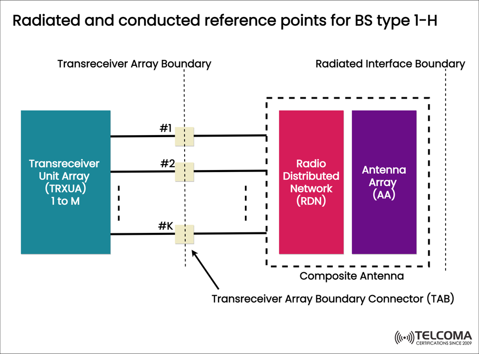
The image uploaded gives a clear look at the radiated and conducted reference points for BS Type 1-H, showing how the Transceiver Unit Array (TRXUA) links to the Radio Distributed Network (RDN) and the Antenna Array (AA) through specific boundaries and connectors.
Next, we’ll dive into the architecture, role, and importance of each piece in this diagram, helping us understand how they all work together to enhance the functionality of 5G base stations.
- Overview of BS Type 1-H in 5G
The 3GPP (3rd Generation Partnership Project) categorizes base stations by their physical integration and interface traits. BS Type 1-H represents a Hybrid Base Station that falls somewhere between fully integrated and fully distributed architectures.
Key Characteristics of BS Type 1-H:
Merges transceiver units with antenna arrays, allowing for some separation.
Supports flexible deployment for Massive MIMO (Multiple Input Multiple Output) systems.
Clearly defines radiated and conducted reference points for testing and meeting standards.
Works with both analog and digital beamforming setups.
This hybrid approach helps network engineers boost radio performance, flexibility, and maintainability, all while meeting the technical requirements set by 3GPP for evaluating base stations.
Components Illustrated in the Diagram
The uploaded image shows three main parts:
Transreceiver Unit Array (TRXUA)
Radio Distributed Network (RDN)
Antenna Array (AA)
These components are divided by key boundaries—the Transreceiver Array Boundary and the Radiated Interface Boundary—which outline where conducted and radiated reference points are.
Transreceiver Unit Array (TRXUA)
The Transreceiver Unit Array (TRXUA) is the digital and RF front-end that handles both sending and receiving signals.
Functions of TRXUA:
Converts baseband signals into RF signals and back again.
Carries out digital pre-distortion, modulation, and filtering.
Manages beamforming weights and calibrates signals.
Links to multiple transmission paths labeled #1 to #K in the diagram.
Each transceiver chain connects to one or more antenna elements, which allows for multi-element control needed for MIMO operations.
Key Features:
Scalable (from 1 to M units).
Works with multiple carriers and is capable of wideband signal processing.
Generally found in the baseband or lower RF section of a 5G gNB.
The transceiver array boundary marks the point where signals shift from a conducted to a radiated environment.
Radio Distributed Network (RDN)
The Radio Distributed Network (RDN) connects the TRXUA to the Antenna Array (AA), acting as an intermediate layer for signal routing and conditioning.
Core Responsibilities:
Distributes RF signals from several transceiver paths to corresponding antenna elements.
Handles signal amplification, phase control, and calibration tasks.
Keeps signal coherence across the array for effective beamforming.
Reduces signal losses using efficient distribution methods (like coaxial, waveguide, or PCB transmission lines).
The RDN can operate in active or passive modes based on whether amplification and control are included.
- Antenna Array (AA)
The Antenna Array (AA) changes electrical signals into electromagnetic waves and vice versa. In BS Type 1-H, this array often sits co-located with the RDN within a composite antenna module.
Functions of the Antenna Array:
Executes beamforming by adjusting phase and amplitude across its elements.
Marks the radiated interface boundary, where the signal exits the hardware and moves through free space.
Enables Massive MIMO, boosting spatial multiplexing gains.
The Antenna Array can include dual-polarized elements to handle multiple frequency bands and support polarization diversity.
Transreceiver Array Boundary and TAB
In the diagram, a dashed vertical line signifies the Transreceiver Array Boundary, separating the TRXUA from the antenna section.
Here, the Transreceiver Array Boundary Connector (TAB) acts as both a physical and logical connection point.
Functions of the TAB:
Offers a reference interface for conducted measurements.
Ensures proper impedance matching between the TRXUA and RDN.
Facilitates testing and calibration at a conducted reference point (#1 to #K).
Each connector (#1, #2, ..., #K) corresponds to a specific signal path or transceiver channel. This interface is vital for checking output power, EVM (Error Vector Magnitude), and spurious emissions before the signals leave the conducted area.
Radiated Interface Boundary
Beyond the composite antenna block, there’s another marked boundary known as the Radiated Interface Boundary. This boundary indicates the shift from conducted to radiated reference points.
At this point:
The signal exits the antenna and transforms into an over-the-air (OTA) electromagnetic wave.
Performance metrics like beam patterns, EIRP (Equivalent Isotropically Radiated Power), and ACLR (Adjacent Channel Leakage Ratio) get measured.
This separation of boundaries allows for performance assessments to be conducted both conductively (internally) and radiatively (externally) in line with 3GPP standards.
Composite Antenna Structure
The Composite Antenna combines the RDN and AA in one mechanical enclosure. This integration:
Simplifies the mechanical design and installation process.
Enhances phase stability between RF and antenna sections.
Diminishes cable losses, boosting overall efficiency.
Permits calibration and testing as a unified system.
This setup is particularly beneficial for Massive MIMO and mmWave base stations, where cutting down on latency and phase distortion is key.
- Conducted and Radiated Reference Points Explained
Reference PointBoundary/LocationPurposeConducted Reference Point (#1 to #K)At Transreceiver Array Boundary (TAB)Used for electrical measurement and calibration of signal quality, power, and EVM.Radiated Reference PointAt Radiated Interface BoundaryDefines the OTA measurement interface for EIRP, beam pattern, and radiated spurious emissions.
This dual reference approach lets engineers validate performance both electrically and electromagnetically, ensuring compliance with 3GPP standards for BS Type 1-H.
- Why BS Type 1-H Architecture Matters
The hybrid BS Type 1-H structure is gaining traction in modern 5G setups because of its balance between integration and modularity.
Advantages:
Streamlines OTA testing and certification.
Eases maintenance and field upgrades.
Supports distributed or centralized processing setups.
Efficiently enables massive MIMO and beamforming.
Cuts down losses and enhances energy efficiency.
This adaptability makes it perfect for mid-band and high-band 5G systems, where compactness, performance, and cost are crucial.
Testing and Validation
5G NR BS Type 1-H requires two main categories of testing:
Conducted Tests – Done at the TRXUA boundary to check parameters like:
* Output power
* EVM (Error Vector Magnitude)
* Spurious emissions
Radiated (OTA) Tests – Carried out at the radiated interface boundary to assess parameters such as:
* Beam pattern verification
* Total radiated power (TRP)
* Total isotropic sensitivity (TIS)
This ensures a comprehensive understanding of both electrical and radiative performance.
Conclusion
The BS Type 1-H architecture bridges traditional and fully integrated base station designs. By clearly defining radiated and conducted reference points, network engineers can accurately evaluate, calibrate, and optimize both RF and antenna performance.
As illustrated in the diagram, the relationship between the Transreceiver Unit Array (TRXUA), Radio Distributed Network (RDN), and Antenna Array (AA) ensures a smooth signal flow from digital processing to over-the-air transmission.
This modular, hybrid strategy is set to shape the future of 5G base station engineering, providing a scalable, efficient, and test-friendly framework for next-gen wireless networks.